2-29
Cisco ASR 1000 Series Aggregation Services Routers Hardware Installation Guide
OL-13208-11
Chapter 2 Cisco ASR 1000 Series Routers Component Overview
Power Supplies for the Cisco ASR 1004 Router
AC/DC Power System Output for Cisco ASR 1006
The power supply output tolerance is defined in Table 2-15 under all combinations of line variation.
Total system consumption per power supply should not exceed 1200 W.
Power Supplies for the Cisco ASR 1004 Router
The Cisco ASR 1004 Router can support up to 735 W output (AC and –48 VDC input). The 735 W power
supply module consists of either an AC or –48 VDC input with two DC voltage outputs: 12 V and 3.3 V.
Each power supply module contains three internal fan modules and provides the forced air cooling for
the chassis. These power supply modules contain a monitor circuit to determine the status of fan speed
and operation along with LED status indicating fan errors.
The system temperature operation is 0 to 40C and –5C to +55C.
• AC System—AC power input is an IEC 320-type power inlet, 15A service connector. The AC input
side contains a front panel with provisions for mounting screw, built in handle to remove the power
supply, three status LEDs, and fans for power supply and system cooling.
• DC System—Three-position terminal block-style connector, with labeled connections for -
(–48/60 V input) and + (–48/60 V Return) and GND (ground symbol). The –48 VDC input side
contains a front panel with provisions for mounting screw, built in handle to extract the power
supply, three status LEDs, and fans for power supply and system cooling.
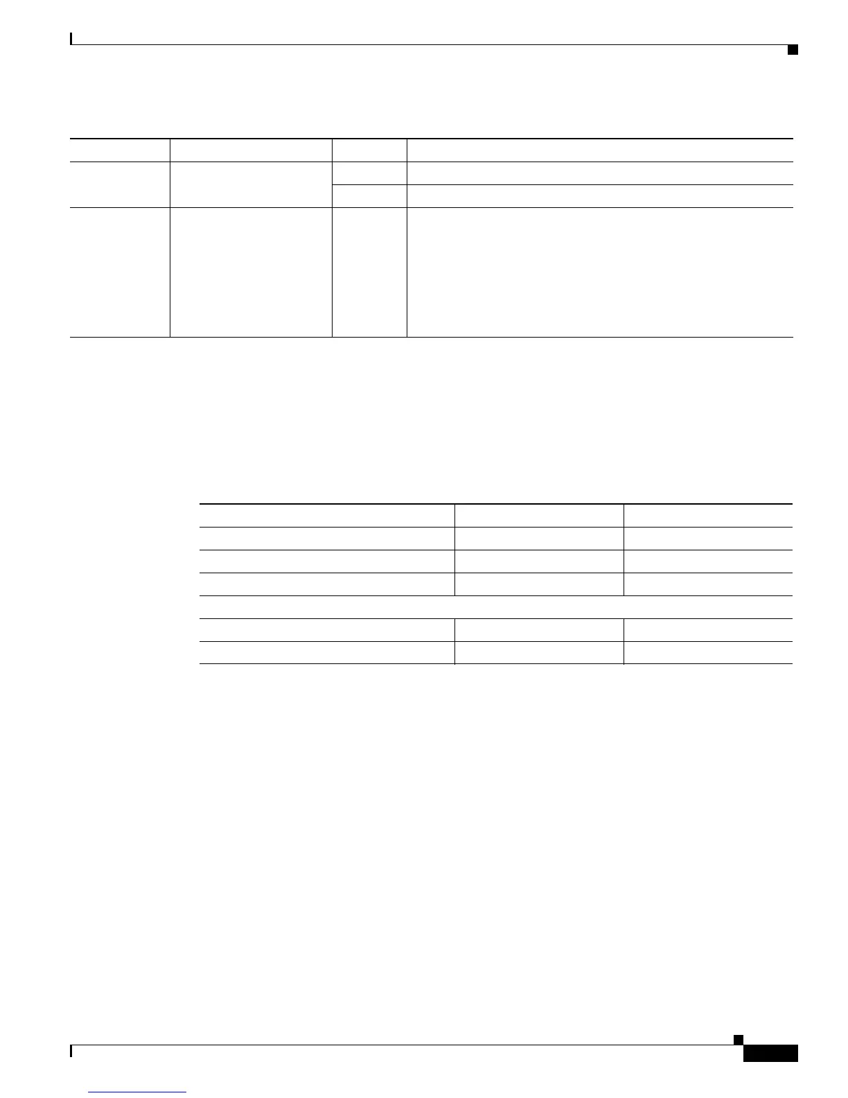
FAN OK A bi-color LED indicates
power supply fan status
Green The LED illuminates s green when all fans are operational.
Red The LED illuminates red when a fan failure is detected.
OUTPUT FAIL Power supply activity Red When the LED is off, it signals that the –48 VDC output voltage
are within the normal operating range. Output voltage between
the minimum and maximum limits will not create an output fail
alarm, and output voltages below the minimum or above the
maximum will create an Output Fail alarm.
When you turn the power supply on, the red LED illuminates for
two to three seconds to test LED operation before going off.
Table 2-14 Cisco ASR 1006 Router –48 VDC Power Supply LEDs (continued)
LED Label LED Color Description
Table 2-15 Cisco ASR 1006 Router Power System Output Voltage and Current
Output Voltage +12 VDC +3.3 V
Minimum 11.80 VDC 3.20 VDC
Nominal 12.00 VDC 3.30 VDC
Maximum 12.20 VDC 3.40 VDC
Output Current
Minimum 2.80 A 0.10 A
Maximum 101.7 A 3.125 A

 Loading...


