2-35
Cisco ASR 1000 Series Aggregation Services Routers Hardware Installation Guide
OL-13208-11
Chapter 2 Cisco ASR 1000 Series Routers Component Overview
Power Supplies for the Cisco ASR 1004 Router
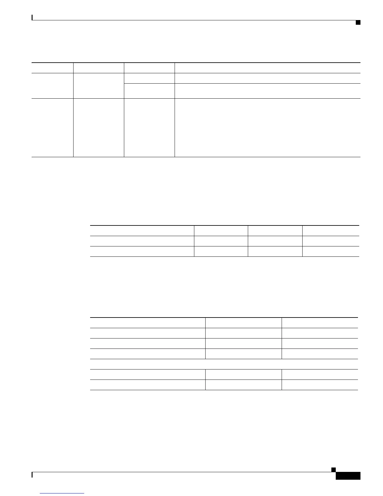
DC Power System Input for Cisco ASR 1004
The –48 VDC power supply operates within specification from –40.5VDC to –72VDC continuously
once the power supply –48 VDC input turn on threshold of –43.5 V has been reached. Table 2-18 shows
the common input ranges for reference only.
AC/DC Power System Output for Cisco ASR 1004
The power supply output tolerance is defined in Table 2-19 under all combinations of line variation.
Total system consumption per power supply should not exceed 735 W.
FAN OK A bi-color LED
indicates power
supply fan status
Green The LED illuminates s green when all fans are operational.
Red The LED illuminates red when a fan failure is detected.
OUTPUT
FAIL
Power supply
activity
Red When the LED is off, it signals that the –48 VDC output voltage are
within the normal operating range. Output voltage between the
minimum and maximum limits will not create an output fail alarm,
and output voltages below the minimum or above the maximum will
create an Output Fail alarm.
When you turn the power supply on, the red LED illuminates for two
to three seconds to test LED operation before going off.
Table 2-17 Cisco ASR 1004 Router –48 VDC Power Supply LEDs (continued)
LED Label LED Color Description
Table 2-18 Cisco ASR 1004 Router –48 VDC Power System Input
Voltage Range (VDC) Minimum Nominal Maximum
Domestic –40.5 –48 –56
International –55 –60 –72
Table 2-19 Cisco ASR 1004 Router Power System Output Voltage and Current
Output Voltage +12 VDC +3.3 V
Minimum 11.80 VDC 3.20 VDC
Nominal 12.00 VDC 3.30 VDC
Maximum 12.20 VDC 3.40 VDC
Output Current
Minimum 2.80 A 0.10 A
Maximum 61.44A 3.125 A
 Loading...


