•
One RJ-45 to RJ-45 crossover cable
•
One RJ-45 to DB-25 (female) adapter
•
One RJ-45 to DB-9 (female) adapter
A crossover cable reverses pin connections from one end to the other. In other words, it connects pin 1 (at
one end) to pin 8 (at the other end), pin 2 to pin 7, pin 3 to pin 6, and so on. You can identify a crossover cable
by comparing the two modular ends of the cable. Hold the cable ends in your hand, side-by-side, with the
tabs at the back. Ensure that the wire connected to the outside (left) pin of the left plug (pin 1) is the same
color as the wire connected to the outside (right) pin of the right plug (pin 8).
Use the following procedure to connect a video terminal to the console port on a route processor.
Each Cisco ASR 1000 Series Route Processor must have a console port connection (typically to a terminal
server) if you are running a redundant configuration in the chassis.
Note
SUMMARY STEPS
1.
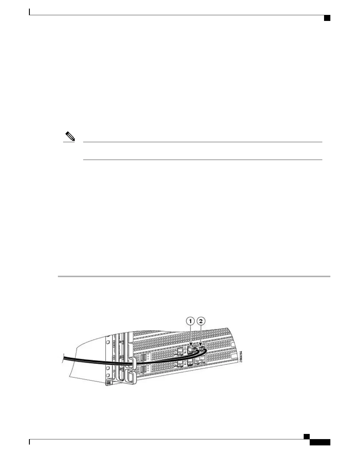
Connect one end of the RJ-45 cables to the serial RJ-45 port (CON) on the Cisco ASR 1000 Series Route
Processor 1 (see the following image).
2.
Run the cable up and through the cable-management bracket and connect the other end of the RJ-45 cable
to the RJ-45 adapter (see the following image).
3.
Connect the adapter to your video terminal to complete the cable connection.
4.
Power on your video terminal.
5.
Configure your video terminal to match the following default console port settings: 9600 baud, 8 data bits,
No parity generation or checking, 1 stop bit, and No flow control.
6.
Go to the Connecting the System Cables, on page 179 to continue the installation.
DETAILED STEPS
Step 1
Connect one end of the RJ-45 cables to the serial RJ-45 port (CON) on the Cisco ASR 1000 Series Route Processor 1
(see the following image).
Figure 55: Console Port Connection on the ASR 1000 Series Route Processor
Cisco ASR 1000 Series Router Hardware Installation Guide
177
Cisco ASR 1006 Router Overview and Installation
Connecting a Terminal to the Cisco ASR 1000 Series RP Console Port

 Loading...


