Captive installation screw6Chassis ESD socket1
DC power supply slot 1
label
7DC power supply slot 0
label
2
Ground lead8DC power supply
Standby/On (|) switch
3
Positive lead9DC power supply LEDs4
Negative lead10Fan5
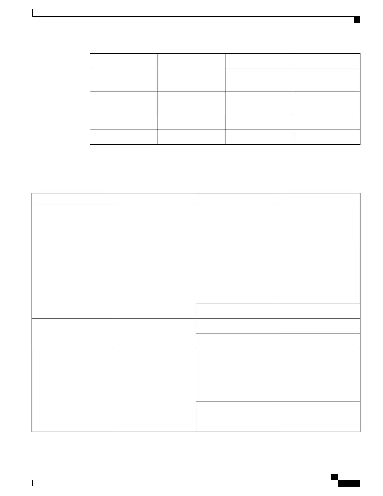
The following table defines the Cisco ASR 1002-F Router DC power supply LEDs on the Cisco ASR 1002-F
Router.
Table 64: Cisco ASR 1002-F Router DC Power Supply LEDs
DescriptionColorLEDLED Label
The DC power supply input
voltage is greater than 43.5
VDC at turn-on and remains
green down to 39 VDC.
GreenPower supply activityINPUT OK
The power supply turns off due
to low input voltage (falls below
39VDC) and indicates that there
is still a hazard present (voltage
on the terminal block). The
LED remains amber and is
active to around 20 V +/-5 V.
Amber
The input is below 15VOff
All fans are operational.GreenPower supply fan status activityFAN OK
A fan failure is detected.Red
The DC output is out of the
specified range. When you turn
the power supply on, the red
LED illuminates for two to
three seconds to test LED
operation before going off.
RedPower supply activityOUTPUT FAIL
The DC output voltage are
within the normal operating
range.
Off
Cisco ASR 1000 Series Router Hardware Installation Guide
285
Cisco ASR 1002-F Router Overview and Installation
Power Supplies in the Cisco ASR 1002-F Router

 Loading...


