USB port—USB
high-speed (480 Mbps)
port used for secure key
storage, VPN credentials
storage, or bulk flash
storage of image and
configuration backup
This USB port is an A
port.
11
T3 RX Port—Receive
port 0
This T3 port uses a
1.0/2.3 RF connector with
75-ohm impedance.
4
STAT—Status LED
12
AUX—RS-232 auxiliary
port
5
PWR—Power LED
13
CON—RS-232 console
port
6
——MGMT—RJ-45
10/100/1000 management
Ethernet port
7
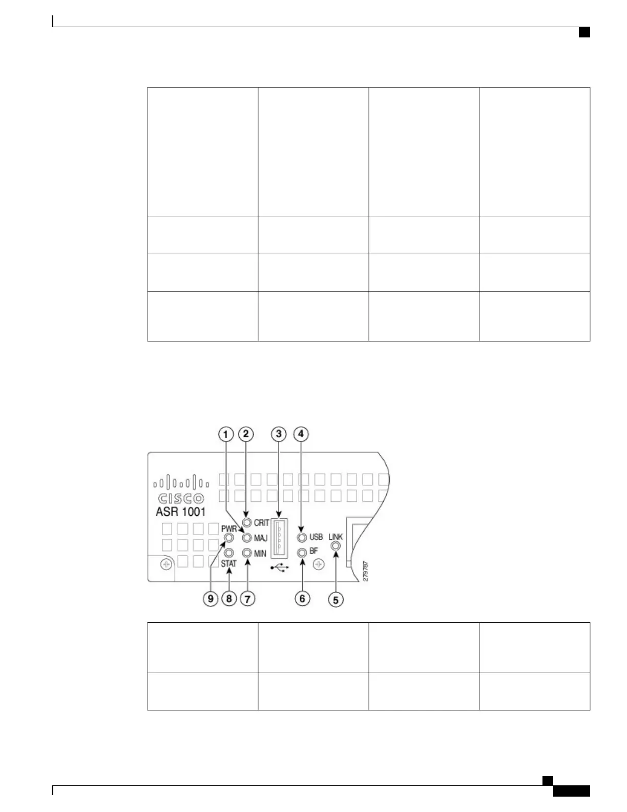
The following figures show the front panel of the Cisco ASR 1001 Router with the various IDCs. The following
image shows the LEDs that are common to all configurations of the Cisco ASR 1001 Router.
Figure 201: Common LEDs for Cisco ASR 1001 Route Processor
BF—Internal bootflash
LED indicates activity of
the EUSB device
6
MAJ LED—major alarm
indicator
1
MIN LED —minor alarm
indicator
7
CRIT LED—critical
alarm indicator
2
Cisco ASR 1000 Series Router Hardware Installation Guide
415
Cisco ASR 1001 Router Overview and Installation
Cisco ASR 1001 Router Architecture
 Loading...


