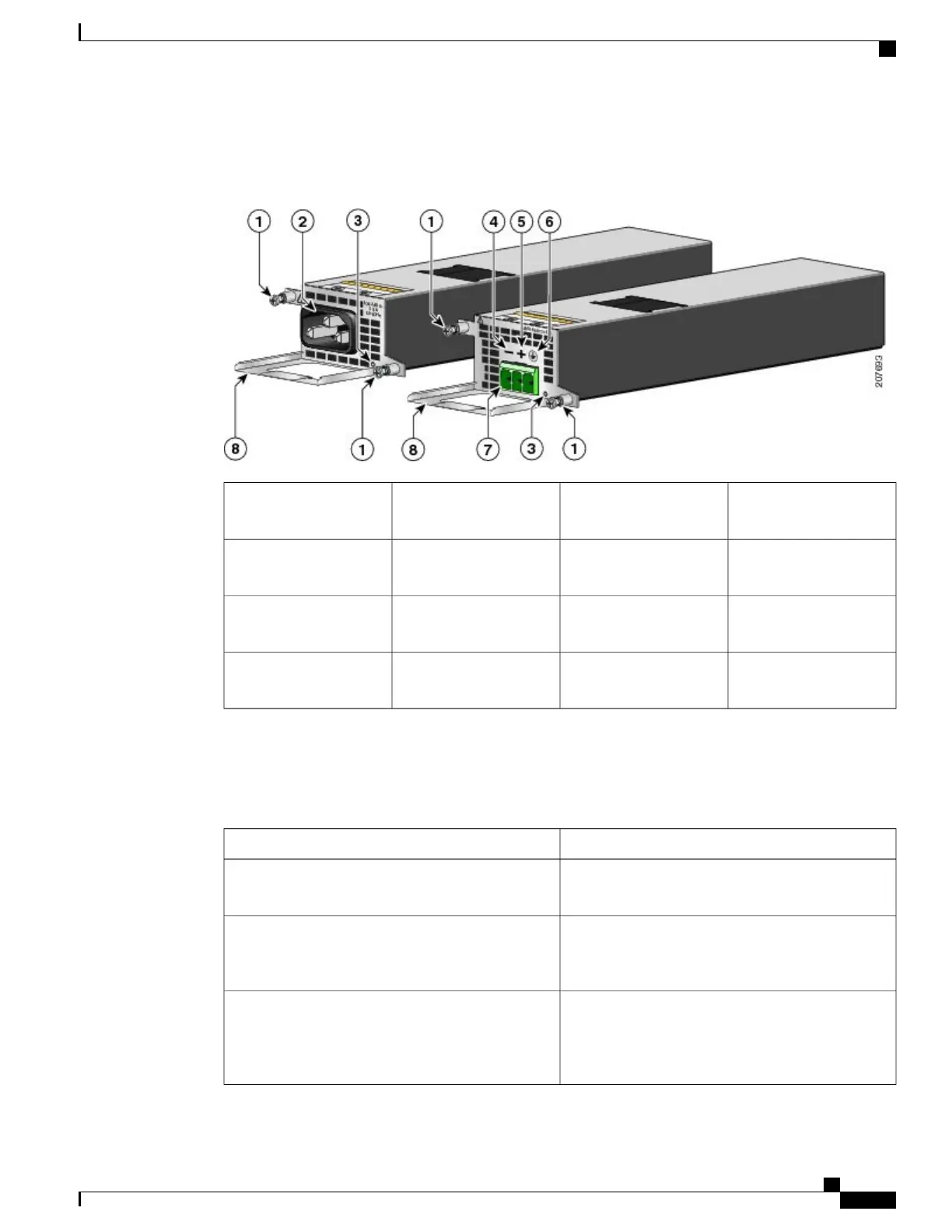
The following image shows both the AC and DC power supplies for the Cisco ASR 1001 Router.
Figure 214: Cisco ASR 1001 Router AC Power Supply and DC Power Supply
DC power supply positive
(+) connection
5AC and DC power supply
fasteners
1
DC power supply ground
symbol
6AC power supply inlet2
DC power supply
terminal block connection
7Power supply LED3
AC and DC power supply
handles
8DC power supply
negative (-) connection
4
The following table describes the power supply LED. The function of the LED is the same for both the AC
and DC power supplies.
Table 88: Cisco ASR 1001 Router AC and DC Power Supply LED
DescriptionLED Color and State
Power output is on and within the normal operating
range.
Solid green
Input power that is within the normal operating range
is being supplied, but the Standby switch is in the
Standby position (and not in the On position).
Blinking green, at the rate of one blink per second
A power supply critical event has occurred, and the
power supply has shut down. The critical event can
be temperature, voltage, current, or fan operating
outside the normal operating range.
Solid amber
Cisco ASR 1000 Series Router Hardware Installation Guide
445
Cisco ASR 1001 Router Overview and Installation
Cisco ASR 1001 Router Power Supply Installation

 Loading...


