Step 8
Use a ratcheting torque screwdriver to torque the terminal block plug captive screw (above the installed wire lead) to
from 0.5 Nm (4.425 lbf in. to 0.6 Nm (5.310 lbf in.), as shown in the following figure.
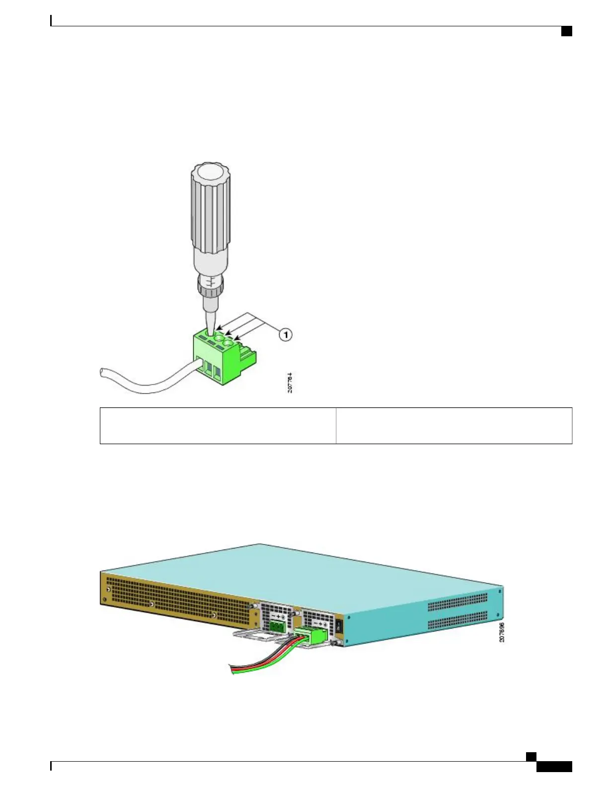
Figure 224: Torquing the DC Power Supply Terminal Block Plug Screws
Torque is from 0.5 Nm (4.425 lbf in.) to 0.6 Nm (5.310 lbf
in.)
1
Step 9
Repeat Step 6 through Step 8 for the remaining two DC input power source wires, the positive lead wire and the negative
lead wire.
The following figure shows how to insert the DC power supply terminal block plug in the block header.
Figure 225: Inserting the DC Power Supply Terminal Block Plug in the Block Header
Cisco ASR 1000 Series Router Hardware Installation Guide
457
Cisco ASR 1001 Router Overview and Installation
Installing DC Input Power on the Cisco ASR 1001 Router

 Loading...


