SUMMARY STEPS
1.
Slip on the ESD-preventive wrist strap that was included in the accessory kit.
2.
Place the power supply Standby switch in the Standby (see the following figure) position.
3.
Turn off the branch circuit breaker before touching terminal screws. Then start loosening the terminal
block screws to remove wires.
4.
Remove the leads from the terminal block in the following order.
5.
Unscrew all of the power supply captive screws.
6.
Grasping the power supply handles, pull the power supply from the chassis.
7.
Replace the –48 VDC power supply within five minutes.
DETAILED STEPS
Step 1
Slip on the ESD-preventive wrist strap that was included in the accessory kit.
Step 2
Place the power supply Standby switch in the Standby (see the following figure) position.
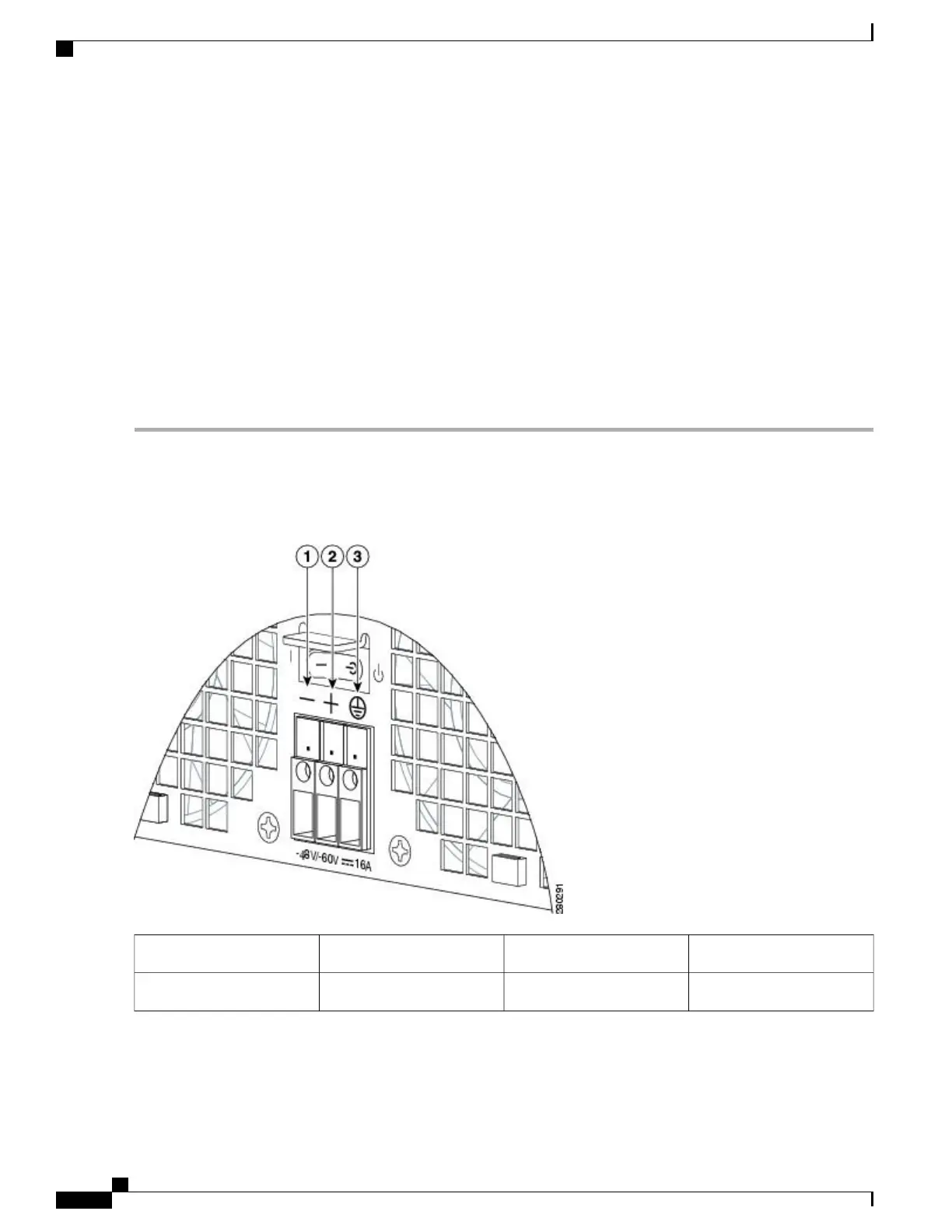
Figure 282: Cisco ASR 1002 Router
–
48 VDC Power Supply Terminal Block
Ground terminal3Negative terminal1
——
Positive terminal2
Cisco ASR 1000 Series Router Hardware Installation Guide
572
Removing and Replacing FRUs from the Cisco ASR 1000 Series Routers
Removing and Replacing a –48 VDC Power Supply in Cisco ASR 1002 Router
 Loading...


