Step 4
The following figure shows the wire strip and insulation location.
Figure 286: Wire Strip and Lead for the +24 VDC Terminal Block
——
Lead wire stripped area1
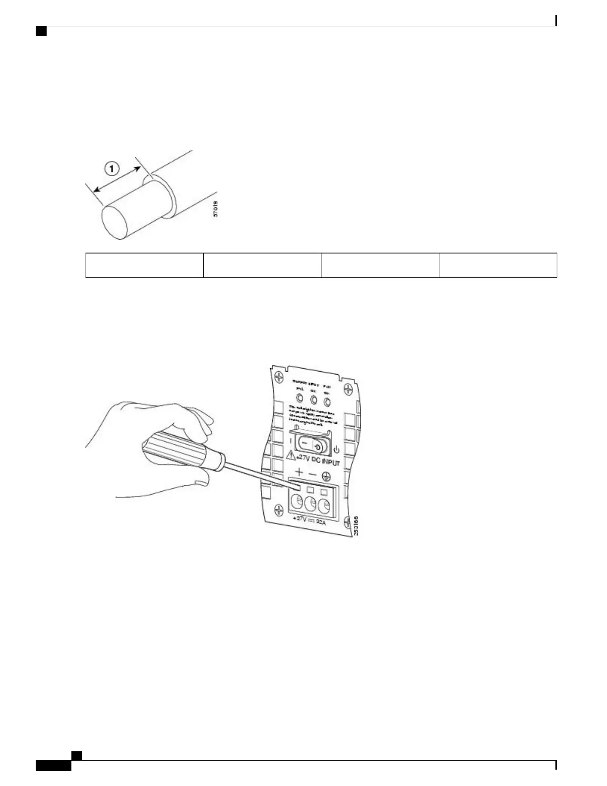
Step 5
Using a 3.5mm screwdriver, insert the screwdriver at an angle to release the spring while you install the stripped lead
wire (see the following figure).
Figure 287: Inserting a Screwdriver into the +24 VDC Power Supply Terminal Block
Step 6
Carefully push the screwdriver at an angle forward until you relieve the spring contact.
Step 7
With the screwdriver still inserted, gently push the lead wire (ground lead first) in until there is no copper wire showing
as shown in the following figure.
Check that there is no copper portion of the lead wire exposed. Only wire insulation must be visible.Caution
Do not install wire into the terminal block that has not had its insulation removed.Caution
Cisco ASR 1000 Series Router Hardware Installation Guide
582
Removing and Replacing FRUs from the Cisco ASR 1000 Series Routers
Removing and Replacing a +24 VDC Power Supply in Cisco ASR 1002 Router
 Loading...


