mm). Do not strip more than the recommended length of wire because doing so could leave the wire exposed from the
terminal block plug. The following figure shows a stripped DC input power source wire.
Figure 307: Stripping the DC Input Power Source Wire
0.39 inch (10 mm) is the recommended wire-strip length
for the connector plug that has raised screw holes. 0.27
inch (7 mm) is the recommended wire-strip length for the
connector plug that does not have raised screw holes.
1
An exposed wire lead from a DC input power source can conduct harmful levels of electricity. Be sure that
no exposed portion of the DC input power source wire extends from the terminal block plug. Statement 122
Warning
Step 6
Identify the positive, negative, and ground feed positions for the terminal block connection. The recommended wiring
sequence is:
a) Ground lead wire (right)
b) Positive (+) lead wire (middle)
c)
Negative (–) lead wire (left)
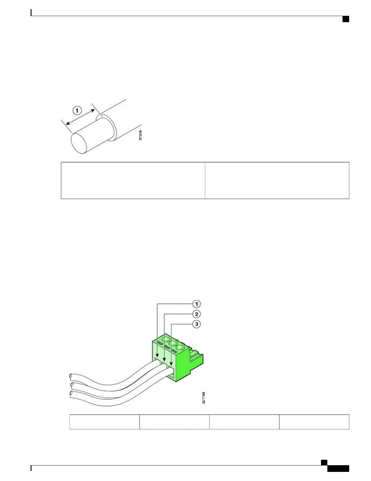
The following figure shows the DC power supply with lead wires.
Figure 308: DC Power Supply with Lead Wires
Ground lead wire3
Negative (–) lead wire
1
Cisco ASR 1000 Series Router Hardware Installation Guide
609
Removing and Replacing FRUs from the Cisco ASR 1000 Series Routers
Removing DC Input Power from the Cisco ASR 1001 Router

 Loading...


