a panel’s speaker off. The function to perform and the panel
upon which it is performed is configured using EHX.
A shielded cable should be used.
The general-purpose inputs operate in one of two modes: the
opto-isolated mode or the non-isolated mode.
The opto-isolated mode requires the externally connected
equipment to provide the current to power the general-purpose
input. The non-isolated mode does not require that the
externally connected equipment powers the general-purpose
input. The current is supplied by a voltage output on the GP IN
connector.
To select a mode, move the J1 jumper on the CPU rear card to
one of two positions. The J1 jumper is located on the inner-
matrix side of the DB-25 connector.
For opto-isolated mode, fit the J1 jumper across pins 1 and
2.
For non-isolated mode, fit the J1 jumper across pins 2 and 3.
It is recommended that the connector is set to the fully opto-
isolated mode.
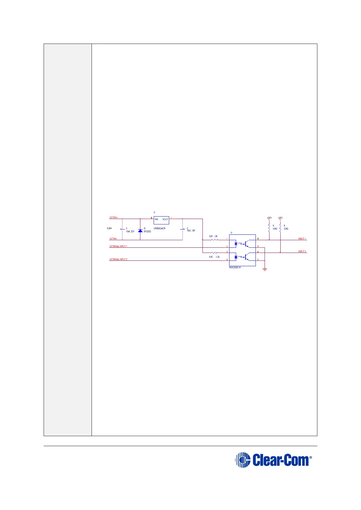
Opto-isolated mode
Figure 4-15: Opto-isolated mode
In this mode, a DC voltage of between 7 and 24 volts is required
at the EXTVIN+ pin with relation to the EXTVIN– pin. To cause
an input to detect an active signal, current must flow from the
relevant input pin.
The external device should draw no current to cause an inactive
input and at least 5 mA to cause an active input. The opto-
isolator drive line contains a 1.5 kOhm resistor to limit the
current through the opto-isolator. Therefore the input pins can
be connected directly to the EXTVIN– level to cause an active
input.
The voltage level at the external input pin should not be allowed
to go below EXTVIN– or above +6 V with respect to EXTVIN–.
Non-isolated mode
To cause an input to detect an active signal in non-isolated
mode, the current must flow from the relevant input pin.
The external device should draw no current to cause an inactive
input and at least 5 mA to cause an active input. The opto-