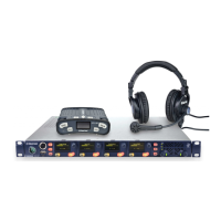
User Guide| Eclipse HX-Median
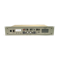
The Eclipse HX-Median matrix frame connects to devices such as the external
computer that runs the EHX configuration software, panels, interfaces, and other
matrices through its rear-panel hardware connectors, often called ports.
These connectors are housed in modular removable panels. Each panel is
associated with a corresponding front-panel circuit card.
5.8.1 Eclipse HX-Median rear connector panels
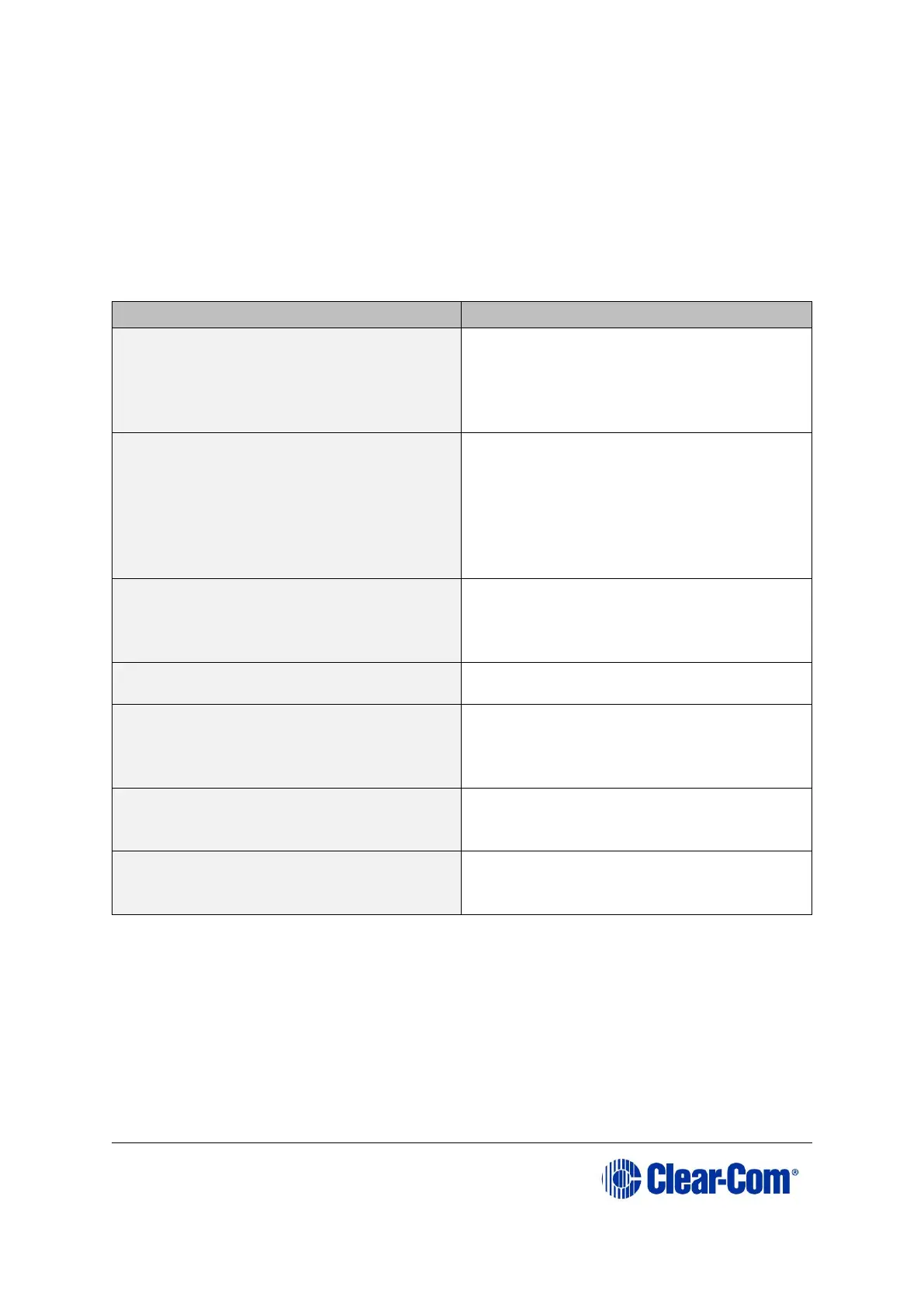
There are six types of rear-connector panels:
A CPU-card rear panel holds the
various connectors associated with the
CPU card, such as the RS-232
connector for the configuration
computer.
Analog port card (MVX-A16)
Analog port-card rear panel holds the
sixteen RJ-45 connectors associated
with its corresponding analog port-
card front panel.
User panels and interface modules
connect to the matrix through this
rear-connector panel.
An E-MADI64 rear card comprises a
MADI fiber connector, MADI input and
output coaxial cable connectors, and a
coaxial Video / Word clock input.
An E-FIB fiber card provides two ports
to connect fiber network cables.
An E-QUE card provides eight RJ-45
ports for connection to wireless
equipment and three RJ-45 ports for
DECT sync and LAN connections.
An IVC-32 card provides a RJ-45 port
for connection to an IP network. No
other ports are used.
An LMC-64 card provides a RJ-45 port
for connection to an IP network. No
other ports are used.
Table 13: Rear connector panels
Note: A blank panel covers an unused slot in the matrix.
5.8.2 Connecting the CPU Card
The rear-connector panel associated with the CPU card holds seven connectors
Note: For a detailed description of each connector, including wiring and pinout
information, see 4.7.1 CPU card interface connectors.