P/N 104075, Rev. 0 Page 11
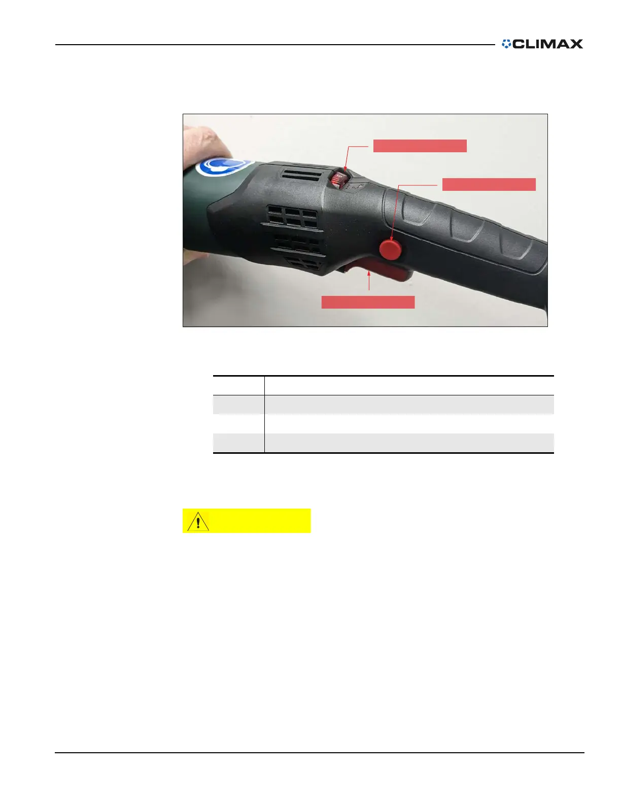
Figure 2-3 shows the motor controls. The motor uses an integrated speed controller
and has a lock function on the control trigger. The speed controller monitors motor
speed to maintain constant motor speed as the load on the spindle increases.
FIGURE 2-3. MOTOR CONTROLS
The motor has built in restart protection and soft start. A flashing light on the speed
control indicates that the trigger needs to be reset before the motor can start.
To avoid damaging the motor, the KM3000 should be used with a circuit
breaker sized to prevent the motor from running above the maximum
current.
Table 2-4 on page 12 shows the approximate spindle speed at specific motor set-
tings.
TABLE 2-3. MOTOR CONTROL IDENTIFICATION
Number Component
1 Speed control
2 Trigger lock
3 Control trigger
CONTROL TRIGGER
TRIGGER LOCK
SPEED CONTROL
1
2
3
 Loading...