P/N 104075, Rev. 0 Page 41
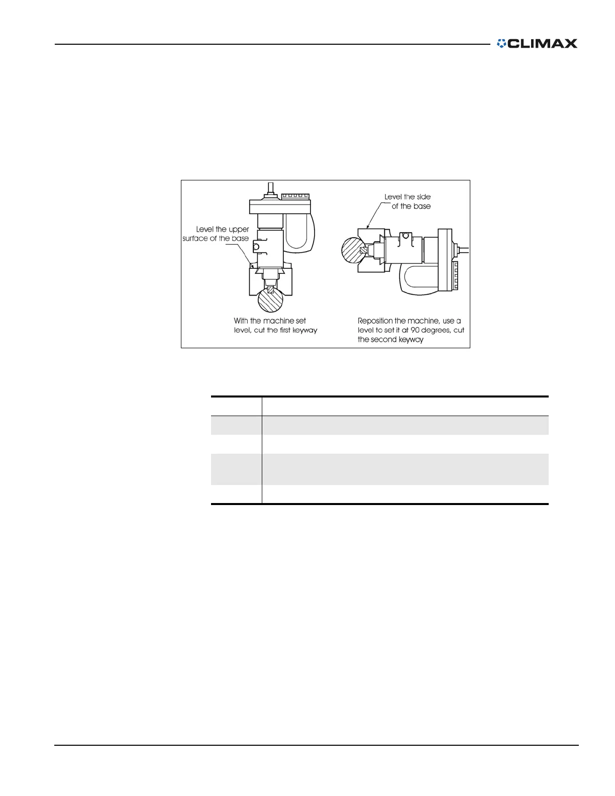
4.6.2 KM3000/KM4000 axially aligned keyways
Do the following for axially aligned keyways:
1. Secure the shaft so it will not rotate.
2. Referring to Figure 4-5 on page 41, mount the key mill on top of the shaft,
setting it level as described in Section 3.4 on page 23.
FIGURE 4-5. AXIALLY ALIGNED KEYWAYS
3. Cut the keyway as described in Section 4.2 on page 33 and Section 4.3 on
page 35.
4. Reposition the machine to the side of the shaft. Place a level on the side of
the base to verify the machine is 90° to the first keyway.
5. Cut the second keyway.
Do the following to cut keyways 120° apart:
1. Secure the shaft so it will not rotate.
2. Mount the key mill to the top of the shaft as described in Section 3.4 on
page 23.
3. Cut the keyway as described in Section 4.3 on page 35.
4. Using an appropriate angle gauge or block, rotate the shaft 120°. Cut the
second keyway.
5. Again, using an angle block, rotate the shaft 120°. Cut the third keyway.
TABLE 4-3. AXIALLY ALIGNED KEYWAYS IDENTIFICATION
Number Component
1 Level the upper surface of the base
2 Level the side of the base
3
Reposition the machine, use a level to set it at 90 degrees, cut
the second keyway
4 With the machine set level, cut the first keyway