Page 24 KM3000 KM4000 Operating Manual
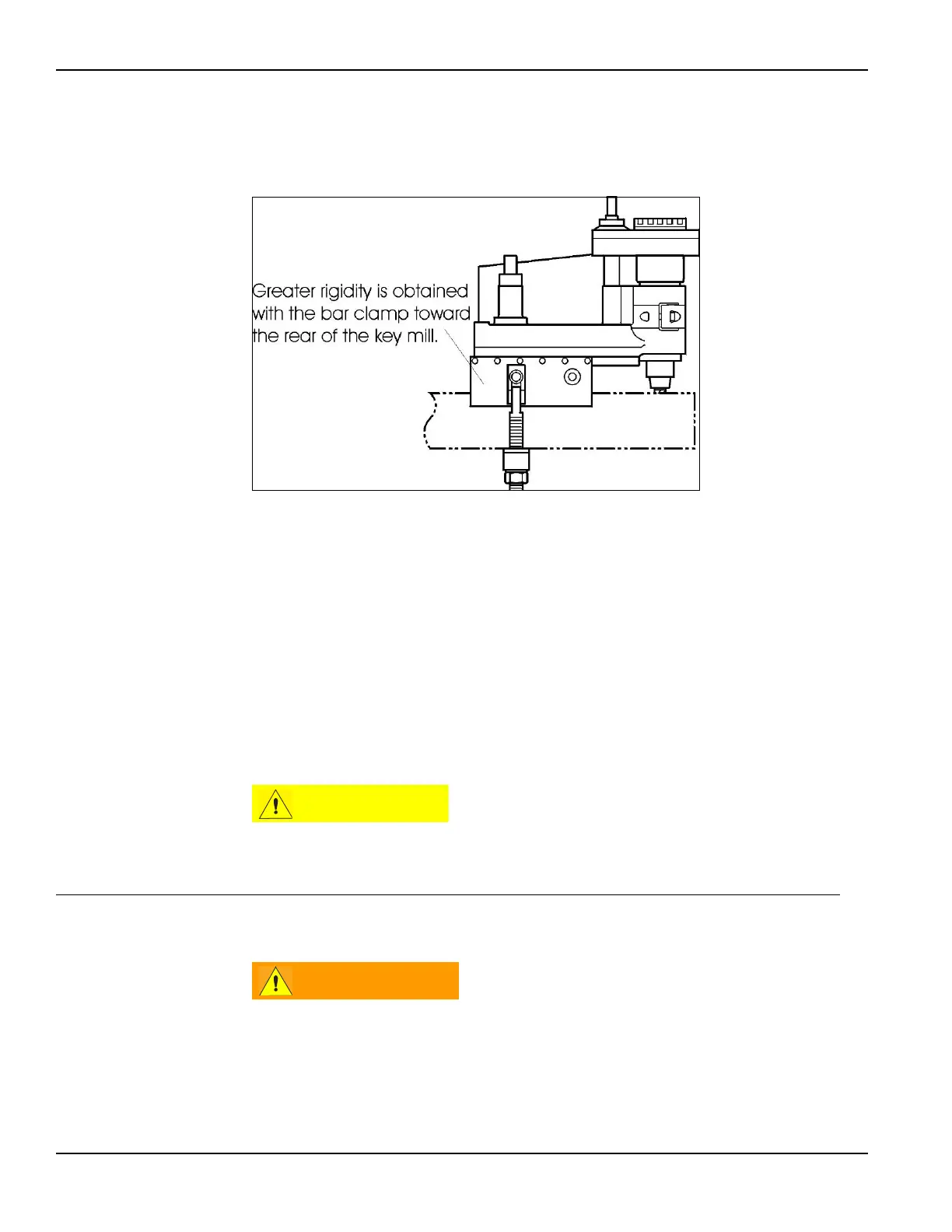
A key mill with the bar clamp attached nearer the rear of the base is the
most rigid setup and gives the best results (see Figure 3-2).
FIGURE 3-2. BAR CLAMP TO REAR OF BASE
2. Hook the clamp bolt assembly over the clamp blocks.
3. Level the machine. Place a precision level on the upper surface of the base
to check that the machine is truly horizontal about the axis of the shaft.
This is especially important when more than one in-line keyway or multi-
ple axially spaced keyways will be cut.
4. Secure the key mill evenly to the shaft by alternating the tightening of one
bar clamp nut then the other.
5. Start tightening at 20 ft-lbs (27.2 Nm) of torque. Torque the clamps evenly
in 10 ft-lb (13.6 Nm) increments.
To avoid damaging the clamp bar do not tighten the clamps over 60 ft-
lbs (81.6 Nm.)
3.5 KM4000 STANDARD SHAFT MOUNTING
Support the machine with rigging while securing it to the workpiece.
Failure to do so will allow the machine to fall, causing death or serious
crushing injury.