P/N 104075, Rev. 0 Page 13
F
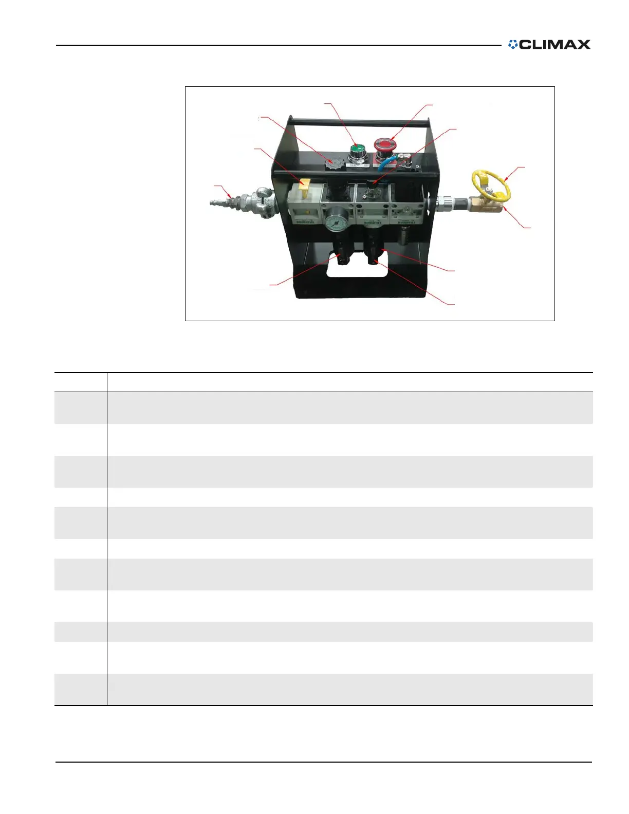
IGURE 2-4. PCU COMPONENTS
TABLE 2-6. PCU CONTROLS IDENTIFICATION
Number Component Function
1
Air hose quick dis-
connect
1
Connects the PCU to the operator’s compressed air source.
2 Air supply lock-out
Isolates air pressure from the machine and provides the ability to lock the valve
closed before performing maintenance.
3 Regulator
Controls the air pressure supplied to the machine. The regulator is preset at the
factory and does not require adjustment.
4 START (system reset) Resets the low-pressure dropout.
5 Emergency STOP
Isolates the supply air and vents the downstream air. Press down to stop the
machine; pull up to reset.
6 Oil drip rate dial Controls the air lubricator drip rate.
7
Speed adjustment
valve
Controls the machine’s rate of rotation and is located on the exhaust of the
pneumatic assembly.
8
Air hose to the
machine
Supplies the air to the machine.
9 Oil reservoir Holds lubricating oil for the machine air motor.
10
Oil reservoir sight
glass
Shows the amount of oil in the reservoir.
11 Filter
Removes foreign particulates from the air supply and protects the downstream
valves and motor.
1.Figure 2-4 shows the H&S quick disconnect. Your disconnect may look different.
 Loading...