Chapter 3. Installation
68
Each 50-pin connector has two sets of pins for each line card slot, Channel A and Channel B. 2-
Wire voice cards require the T and R connections. 4-Wire voice cards require T, R, T1, and R1
connections. E&M signalling requires the addition of the E&M connections.
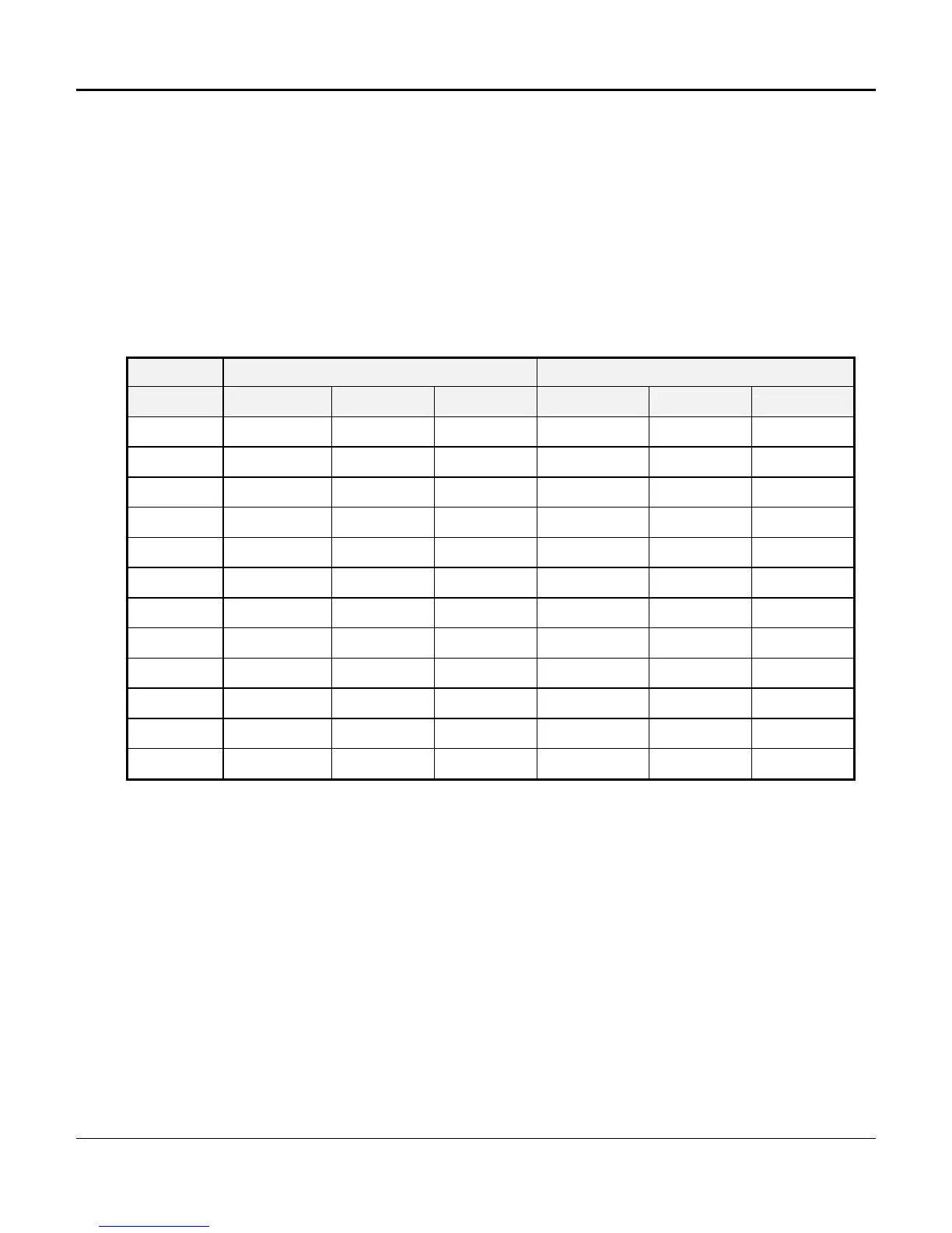
Tables on the following pages give detailed instructions connections appropriate for the 8-, 12-,
and 24-slot D/I Mux III shelf models. Make the connections to the 50-pin connectors according to
Tables 3-9 and 3-10. Table 3-11 shows the color coding for the 50-pin connector. (For more
information on connector pinouts, refer to Appendix E. Wiring and Cable Tables.)
Table 3-9. 50-Pin Connector Pin-Outs
for the 8- and 12-Slot Shelves
Card Slot Channel A Channel B
R & T R1 & T1 M & E R & T R1 & T1 M & E
1 P1 - 1/26 P2 - 1/26 P3 - 1/26 P1 - 13/38 P2 - 13/38 P3 - 13/38
2 P1 - 2/27 P2 - 2/27 P3 - 2/27 P1 - 14/39 P2 - 14/39 P3 - 14/39
3 P1 - 3/28 P2 - 3/28 P3 - 3/28 P1 - 15/40 P2 - 15/40 P3 - 15/40
4 P1 - 4/29 P2 - 4/29 P3 - 4/29 P1 - 16/41 P2 - 16/41 P3 - 16/41
5 P1 - 5/30 P2 - 5/30 P3 - 5/30 P1 - 17/42 P2 - 17/42 P3 - 17/42
6 P1 - 6/31 P2 - 6/31 P3 - 6/31 P1 - 18/43 P2 - 18/43 P3 - 18/43
7 P1 - 7/32 P2 - 7/32 P3 - 7/32 P1 - 19/44 P2 - 19/44 P3 - 19/44
8 P1 - 8/33 P2 - 8/33 P3 - 8/33 P1 - 20/45 P2 - 20/45 P3 - 20/45
9 P1 - 9/34 P2 - 9/34 P3 - 9/34 P1 - 21/46 P2 - 21/46 P3 - 21/46
10 P1 - 10/35 P2 - 10/35 P3 - 10/35 P1 - 22/47 P2 - 22/47 P3 - 22/47
11 P1 - 11/36 P2 - 11/36 P3 - 11/36 P1 - 23/48 P2 - 23/48 P3 - 23/48
12 P1 - 12/37 P2 - 12/37 P3 - 12/37 P1 - 24/49 P2 - 24/49 P3 - 24/49
 Loading...