ION
®
-E Series Hardware Installation Guide M0201AA
Page 16 © June 2017 CommScope, Inc.
WCS-2 and WCS-4 Subracks and Modules
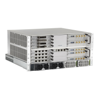
Thealphanumericnumberingoftheslotsandportscorrespondtotheslotandportidentificationusedinthe
ION-EGUI,asshownin
Figure3-2.
Figure 3-2. Slot and Port Designations in the ION-E GUI
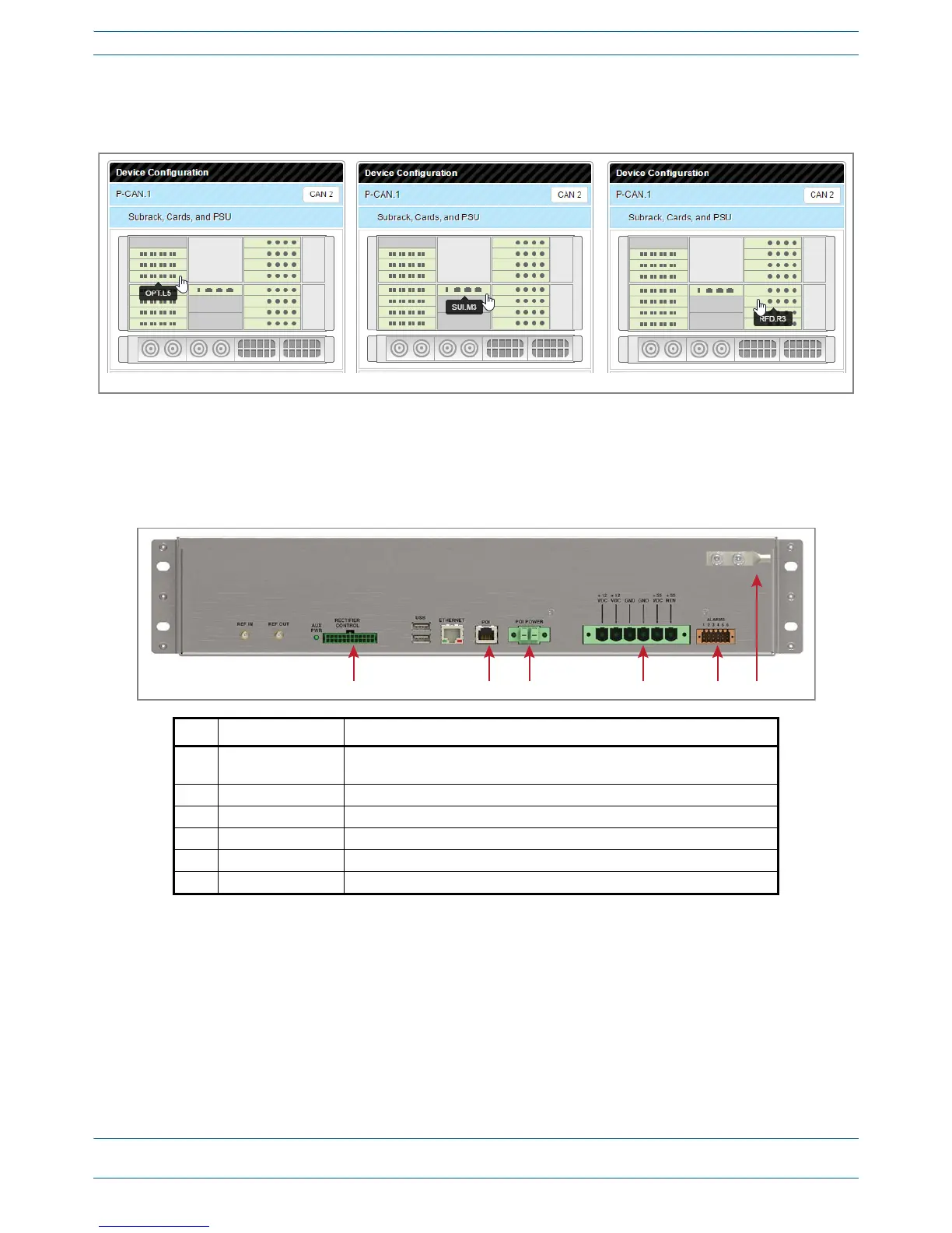
WCS Subrack Back Panel Connectors
UNRESOLVED: This looks like it is the rear of the WCS-2. Are the connectors laid out the same on WCS-4?
Ref. # Component Description
1 Rectifier Control
connector
24-pin connector for PSU communication
2 POI connector POI Communication
3 POI Power connector 12 Vdc to e-POI Subrack
4 Power connector Inputs to the 12 Vdc Module and the 57 Vdc Module
5 Alarm connector Dry contact input and output; see "WCS Subrack Alarm Connector” on page 17.
6 Ground stud Ground (earth) connection to the Power Supply Subrack