M0201AA ION
®
-E Series Hardware Installation Guide
© June 2017 CommScope, Inc. Page 27
Installing Subracks and PSUs in an Equipment Rack
Install the CAN and TEN Cards
1 Ifnecessary,removetheblankfaceplate(s)fromtheslot(s)inwhichtheDARTistobeinstalled.
a Loosenthetwothumbscrewsthatsecuretheblankfaceplate(s)totheHostUnitchassis.
b CarefullywithdrawtheblankDARTfaceplatefromthechassis.
c Reservetheblankfaceplatesforfutureuse.
2 Slidethecardintotheslotthatitwilloccupy,andthenpushitbackuntilitsfaceplateisflushagainstthe
subrackchassis.
3 Tightenthetwothumbscrewsthatsecurethecardinthesubrackchassis.
4 Donotleaveanyunoccupiedslotsopen;replaceblankfaceplates,asnecessary..
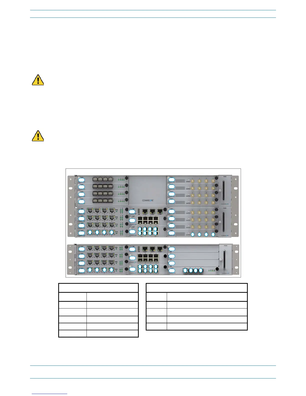
5 FollowtheruleslistedbelowtoinstalltheCANandTENcardsintotheWCS-2orWCS-4Subrack.
Do not remove the blank faceplate from a slot in which a card will not be installed. To maximize airflow
through the WCS chassis, blank panels must be installed in all empty Card slots.
To maximize airflow through the WCS chassis, blank panels must be installed in all empty Card slots. If
additional blank faceplates are required, you can order them from CommScope (see "Contacting DCCS
Global Technical Support” on page 126).
Placement of cards to create a CAN Placement of cards to create a TEN
2
Card Slot Install this Card Card Slot Install this Card
L5 - L8 OPT Card R1 OPT Card; use Port 1 to connect to the CAN
L1 - L4
1
CAT Card L1 - L4 CAT Card
R1 - R8 RFD Card M3 SUI Card
M3 SUI Card M1 - M2 AUT Card (optional)
M1 - M2 AUT Card (optional)
1 Can also be used for additional OPT
Cards.
2 TENs do not support RFD Cards.