EasyManuals Logo

CommScope ION-E Series User Manual

CommScope ION-E Series
64 pages
To Next Page IconTo Next Page
To Previous Page IconTo Previous Page
Page #23 background imageLoading...
Page #23 background image
M0201AA ION
®
-E Series Hardware Installation Guide
© June 2017 CommScope, Inc. Page 17
WCS-2 and WCS-4 Subracks and Modules
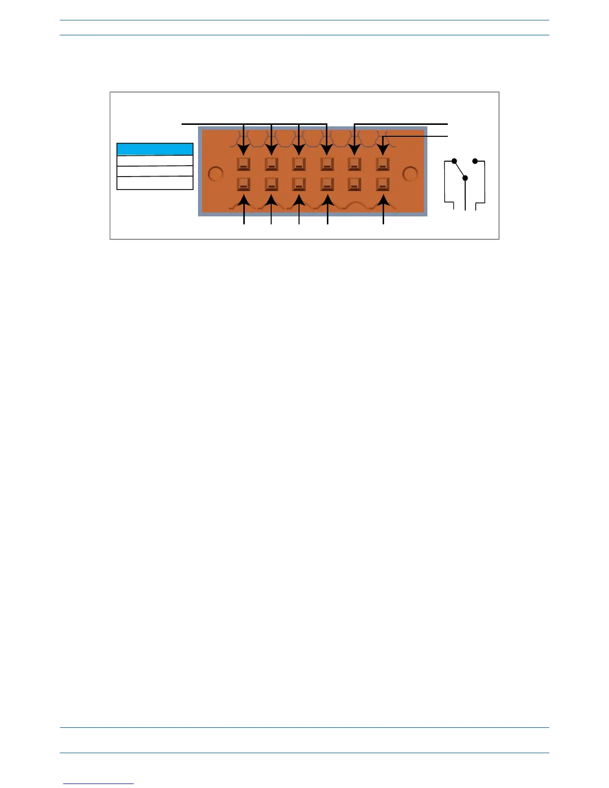
WCS Subrack Alarm Connector
TheAlarmconnectoronthebackpaneloftheWCS-4andWCS-2subrackshas
fouropto-isolated(chassis-groundreferenced)drycontactinputstomonitorexternaldevices
oneSummaryAlarmRelaythatenergizeswhenspecificalarmsaretriggered—thethresholdsofwhich
areshownintheprecedinggraphic.[
Which alarms? We need to match the Summary Alarms shown above with
the actual corresponding alarms.
]
NC
COM
NO
ALARMS
12345 6
Relay COM
GND
IN 1 IN 2 IN 3 IN 4 Relay NO
Relay NC
Summary Alarm
2 A max
30 Vdc max
125 Vac max

Table of Contents

Questions and Answers:

Question and Answer IconNeed help?

Do you have a question about the CommScope ION-E Series and is the answer not in the manual?

CommScope ION-E Series Specifications

General IconGeneral
BrandCommScope
ModelION-E Series
CategoryMulti-service Platforms
LanguageEnglish