Home
CommScope
Multi-service Platforms
ION-E Series
CommScope ION-E Series User Manual
4
of 1
of 1 rating
64 pages
Give review
Manual
Specs
To Next Page
To Next Page
To Previous Page
To Previous Page
Loading...
M0201AA
ION
®
-E Series Hardware Installation Guide
© June 2017 CommScope, Inc.
Page 25
Installing Subracks and PSUs in an Equipment Rack
Connect the Subrack and PSU Po
wer and Communication Cables
1
Connecttherear-panelpower,co
mmunication,andcontrolcables
assho
wninthefollowinggraphic.
e-POI
WCS
PSU
T
o/From eNodeB
e-POI communicaons
e-POI power
Subrack gr
ound
(requir
ed)
WCS D
C po
wer
Subrack gr
ound
(requir
ed)
Recfier con
trol
Subrack gr
ound
(requir
ed)
85 to 264 V
ac
30
32
Table of Contents
Default Chapter
3
Table of Contents
3
Using this Document
7
Document Revision History
8
Document Cautions and Notes
9
Abbreviations Used in this Guide
10
ION-E Series Hardware Overview
11
Chapter Topics
12
ION-E Series System Overview
12
Safely Working with ION-E Hardware
15
Equipment Symbols with CE Compliance
15
Health and Safety Precautions
15
Property Damage Warnings
16
Compliance and Standards Certification
17
FCC RF Exposure Requirements
17
EMC Standards
17
FCC and IC Standards
18
WCS-2 and WCS-4 Subracks and Modules
19
Chapter Topics
20
WCS-2 and WCS-4 Subracks and Modules
20
WCS Subrack Front Panel Card Slots and GUI Identification
21
WCS Subrack Back Panel Connectors
22
WCS Subrack Alarm Connector
23
WCS Fan Modules and Filters
24
System User Interface Card (SUI)
25
RF Donor Card (RFD)
26
Optical Transport Card (OPT)
27
Copper Transport Card (CAT)
28
Auxiliary Unit Transport Card (AUT)
29
Installing Subracks and Psus in an Equipment Rack
30
Rack-Mounting the Subracks and PSU
30
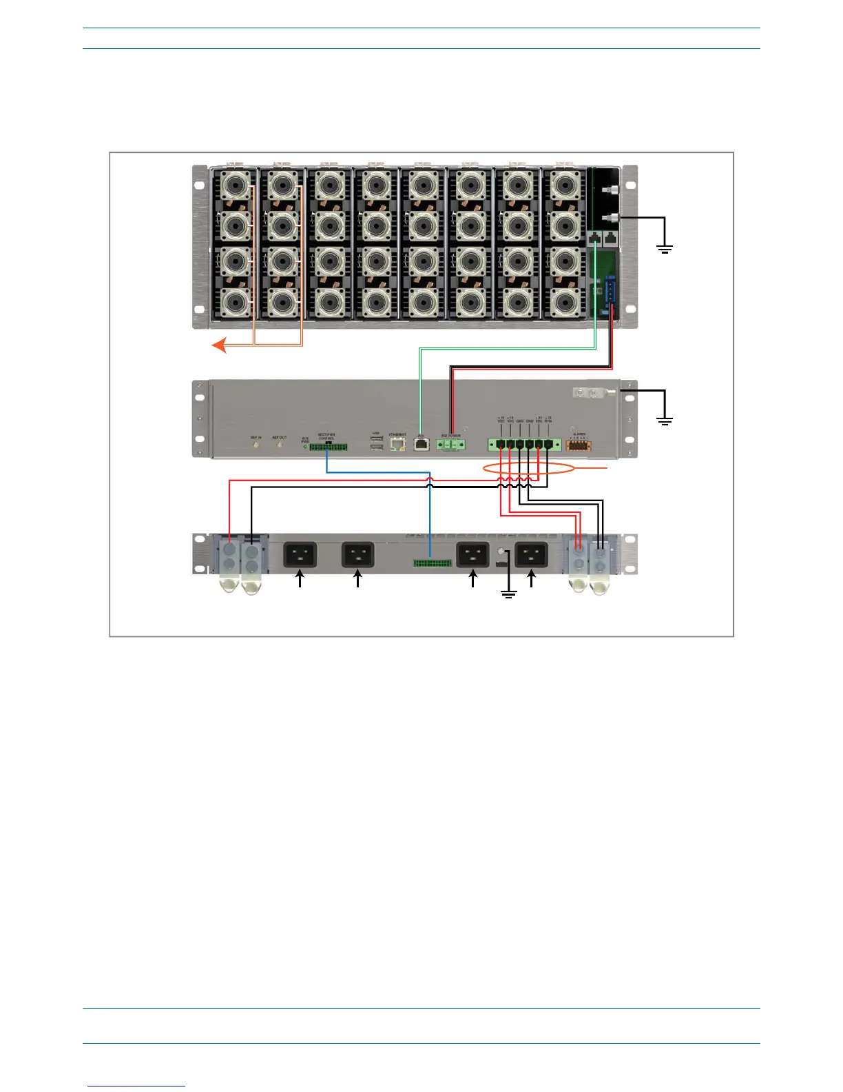
Connect the Subrack and PSU Power and Communication Cables
31
Install the CAN and TEN Cards
33
Install SFP+ Transceivers in the OPT Cards
34
Connect the RFD Cards
35
Connect the CAT Cards
36
Connect the AUT Cards
38
Point of Interface (E-POI) Subracks
41
Chapter Topics
42
Point of Interface (E-POI) Subrack
42
E-POI Subrack Back Panel Connectors
42
Interface Card (IFC)
43
E-POI Module
44
Installing an E-POI Subracks and Modules
45
Removing an E-POI Module from an E-POI Subrack
46
E-POI Subrack and Component Specifications
47
Power Supply Unit (PSU)
49
Chapter Topics
50
Power Supply Unit (PSU)
50
PSU Modules and Connectors
50
12 VDC Power Module Leds
51
VDC Power Module Leds
52
Installing Psus
53
Table of Contents
55
Universal Access Points
55
Chapter Topics
56
Identifying Uaps in the ION-E Software
56
Uaps and UAP-N25S
57
Uap-X
58
Installing Uaps
59
Using the UAP Ceiling Mount Assembly (PN 7683182-00)
59
Required Tools for a Standard UAP Ceiling Mount
59
Unpack and Inspect the Ceiling Mount Assembly
59
Standard Ceiling Mount Overview
60
Standard Ceiling Mount Installation Steps
61
Mounting a UAP Using a UAP Quick Release Ceiling Mount Kit
63
Required Tools for a Quick Release Ceiling Mount Kit
63
Unpack and Inspect the Quick Release Ceiling Mount Kit
64
Overview of Using a Quick Release Ceiling Mount Kit
64
4
Based on 1 rating
Ask a question
Give review
Questions and Answers:
Need help?
Do you have a question about the CommScope ION-E Series and is the answer not in the manual?
Ask a question
CommScope ION-E Series Specifications
General
Brand
CommScope
Model
ION-E Series
Category
Multi-service Platforms
Language
English