Mentor ll User Guide 9
Issue Number: 12 www.controltechniques.com
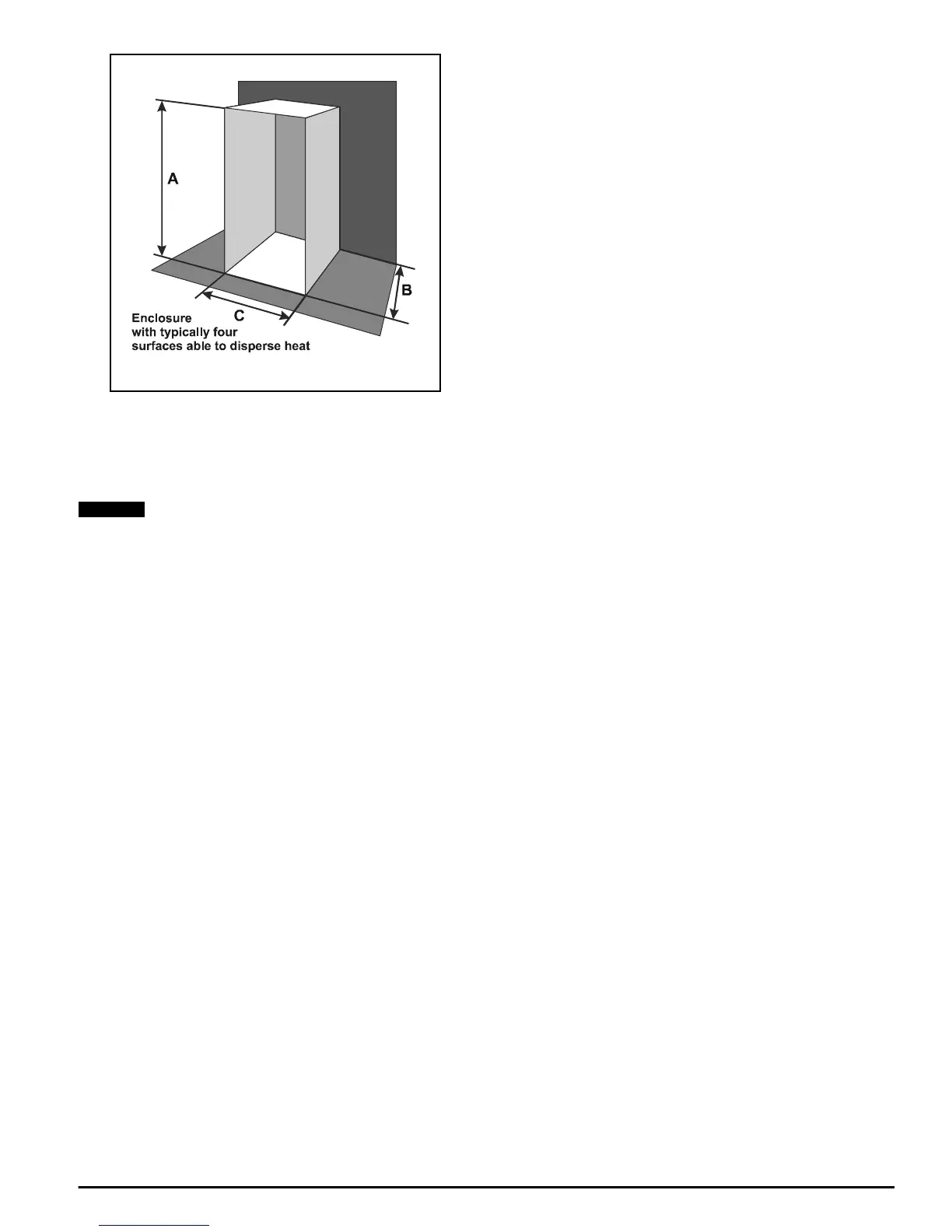
Figure 5-2
To find the effective heat-conducting area
The values of the variables appropriate to the above specification are:
P
l
400W (losses)
It is essential to include any other heat-generating equipment in the
value for PI.
T
i
40
o
C (for all Mentor II Drives)
T
amb
25
o
C
k 5.5 (typical value for 2mm (0.1in) sheet steel, painted)
To find the dimensions of the enclosure
If an enclosure is to be fabricated to suit the installation, there is a free
choice of dimensions. Alternatively, it may be decided to choose an
enclosure from a range of standard products. Either way, it is important
to take into account the dimensions of the Drive, and the minimum
clearance of 100mm (4in) round it (Figure 5-1).
The procedure is to estimate two of the dimensions - the height and
depth, for example - then calculate the third, and finally check that it
allows adequate internal clearance.
The effective heat-conducting area of an enclosure as illustrated in
Figure 5-2, located on the floor and against one wall is:
A
e
=2AB + AC + BC
Where:
A is the enclosure height
B is the depth, front to back
C is the width.
Suppose the enclosure height A is 2.2m (7ft 3in), and the depth B is
0.6m (2ft), as a first estimate. The actual figures chosen in practice will
be guided by available space, perhaps, or standard enclosure sizes.
Since A
e
, A,andB are known, the dimension to be calculated is C.The
equation needs to be rearranged to allow C to be found, thus:
A
e
-2AB = C (A + B)
or,
Clearance on either side of the Drive must be checked. The width of the
Drive is 250mm (10in). Clearance of 100mm (4in) is required on either
side. So the minimum internal width of the enclosure must be 450mm, or
0.45m (18in). This is within the calculated width, and therefore
acceptable. However, it allows limited space for any equipment to either
side of the Drive, and this may be a factor in deciding the proportions of
a suitable enclosure. If so, modify the calculated value of C to allow for
other equipment, and re-calculate either of the other two dimensions by
the same method.
If an enclosure is to be selected from a stock catalogue, the
corresponding surface area should be not less than the figure
calculated above for A
e
.
As a general rule, it is better to locate heat-generating equipment low in
an enclosure to encourage internal convection and distribute the heat. If
it is unavoidable to place such equipment near the top, consideration
should be given to increasing the dimensions of the top at the expense
of the height, or to installing internal circulation fans with Drives which
are not equipped with a built-in fan to ensure air circulation.
Enclosure ventilation
If a high Ingress Protection rating is not a critical factor, the enclosure
canbesmallerifaventilatingfanisusedtoexchangeairbetweenthe
inside and the outside of the enclosure.
To calculate the volume of ventilating air, V, the following formula is
used:
Where:
V is the required air flow in m
3
h
-1
.
To find the ventilation required for an M210 Drive
P
l
400W
T
i
40
o
C (for Mentor II Drives)
T
amb
25
o
C(forexample)
Then:
NOTE
A
e
400
5.5 40 25–()
---------------------------------
4.85m
2
52ft
2
()==
C
A
e
2AB–
AB+
--------------------------
=
C
4.85 2 2.2× 0.6×()–
2.2 0.6+
-------------------------------------------------------
0.8m 2ft7in()approx==
V
3.1P
1
T
i
T
amb
–
-------------------------
=
V
3.1 400×
40 25–
------------------------
83m
3
h
1–
2930ft
3
h
1–
()==