Mentor ll User Guide 3
Issue Number: 12 www.controltechniques.com
3Introduction
Mentor II is the latest family of advanced, fully microprocessor-controlled
DC variable speed industrial Drives. The range of output current is from
25A to 1850A. All sizes share control, monitoring, protection and serial
communications features.
All units are available alternatively in either single-ended or four-
quadrant configuration. Single-ended Drives provide forward run
operation only. Four-quadrant Drives are fully-reversible. Both types
offer comprehensive control of motor speed and/or torque, the four-
quadrant Drives providing full control in both directions of rotation.
Operating parameters are selected and changed either at the keypad or
through the serial communications link (interface). Access for writing or
changing parameter values can be protected by the three-level security
code system.
3.1 DC motor control
The functions of a DC motor which must be controllable for practical use
are the speed, the torque delivered, and the direction of rotation. Speed
is proportional to armature back-emf and inversely proportional to field
flux. Torque is proportional to armature current and field flux. Direction of
rotation is simply a matter of the relative polarities of the armature and
field voltages. It follows that it is necessary to control:
1. The armature voltage; back-emf is a component of armature voltage.
Thus, assuming the field to be constant, control of armature voltage
provides complete control of speed up to the point where the voltage
reaches the maximum value for which the armature is designed.
Armaturecurrentisalsoafunctionofarmaturevoltage,sothat
within the speed range up to maximum voltage, torque is controlled
by voltage also. Provided that the field is fully-excited, the availability
of maximum torque is normally maintained from zero speed up to
armature voltage maximum (base speed).
2. The field voltage; this determines the field current and, in
consequence, field flux. If field voltage can be varied independently
of the armature voltage, speed can be increased at full power (full
armature voltage) beyond the point where the applied armature
voltage and current are at maximum. Since torque is directly
proportional to field flux, maximum torque is reduced if speed is
increased by weakening the field.
Basically, therefore, a variable speed DC Drive is a means of controlling
the voltage applied to the armature of the motor, and thus the current
delivered to the motor. The Drive may be equipped with means for
control of the field if speeds higher than base speed are required.
Separatecontrolofthefieldwithintheoperatingrangeuptobasespeed
can be exploited also, to obtain extended control of speed and torque for
more-complex motor applications. If a suitable feedback is available,
position control becomes possible.
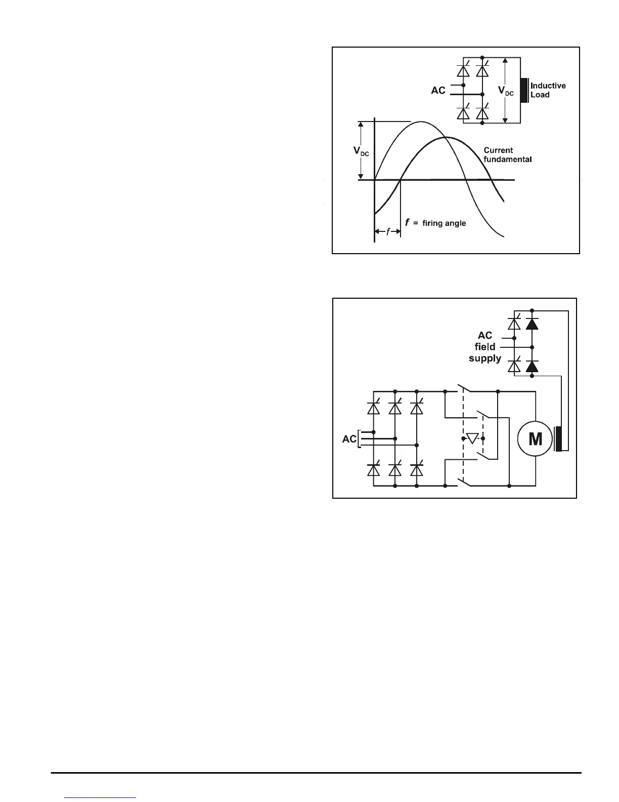
3.2 Principles of the variable speed drive
A single phase voltage applied to a fully-controlled thyristor (SCR) bridge
and a resistive load produces an intermittent flow of current which is
started by the firing of the thyristor (SCR), and stopped as a result of the
supply voltage passing through zero at the end of each half cycle.
Maximum voltage is delivered when the firing angle is fully advanced,
that is, when f in Figure 3-1 becomes zero. Retarding the firing angle
reduces the current output. When the load is inductive, such as a motor,
or the firing angle is sufficiently advanced, current becomes continuous .
The fundamental of the current characteristically lags behind the voltage
due partly to the inductive nature of the load and partly due to firing
angle delay.
Figure 3-1 Behavior of a single-phase fully-controlled thyristor
rectifier (SCR) supplying a highly-inductive load
Figure 3-2 Typical arrangement for reversing a “single-ended” DC
drive using an interlocked pair of contactors in the armature circuit
3.3 Reversing
Reversal of rotation is done in one of two ways, dependent on the type of
Drive bridge configuration. The simplest fully-controllable arrangement
of thyristor (SCR) bridge configuration to operate from a 3-phase AC
supply is a full-wave bridge but this is not capable of reversing the output
polarity. This type, which is called single-quadrant or single-ended,
requires a means of switching the motor terminals externally as shown in
Figure 3-2 if reversing is required. For some applications this simple
system is an adequate practical solution.
If, however, the motor application is such that it demands complete
control of motor operation in both directions, with the ability to reverse
motor torque rapidly and frequently, two anti-parallel bridges must be
used, Figure 3-3. This configuration provides full control of forward and
reverse Drive and forward and reverse braking without the need for
reversing contactors, and is called four-quadrant, Figure 3-4.
If braking is required with a single-ended Drive, an external circuit has to
be provided, Figure 3-5 (dynamic braking). In this case, deceleration is
neither controlled nor linear.