Mentor ll User Guide 19
Issue Number: 12 www.controltechniques.com
6.6 Terminals classified
Analog outputs
Terminal block TB2, terminals 11 to 14 inclusive.
Armature current indication, 5mA Drive capability.
Three undedicated outputs, 5mA Drive capability. Output voltage range -
10V to +10V.
Analog inputs
Terminal block TB1, terminals 3 to 10 inclusive.
Five undedicated inputs, impedance 100kΩ. Input voltage range -10V to
+10V.
Dedicated inputs for motor thermistor (thermal) or thermostat (trip level
3kΩ, reset 1.8kΩ approx.) and tachogenerator (tachometer) feedback.
Digital outputs
Terminal block TB2, terminals 15 to 19 inclusive.
Terminal block TB4, terminals 34 to 39 inclusive.
Five undedicated open-collector outputs.
Maximum current-sinking capability 100mA.
One undedicated relay output.
Dedicated Drive ready relay output.
Maximum relay current at:
250V AC 2.2A
110V AC 5A
5V DC5A
When using digital outputs with an external 24V supplier and an external
load, such as a relay coil, a fly wheel diode should be connected across
the load.
Digital inputs
Terminal block TB3, terminals 21 to 30 inclusive.
Terminal block TB4, terminals 31, 32.
Nine undedicated inputs, impedance 10kΩ.
Drive enable signal - operates directly on the output gate-pulse circuits
for safety. Delay 30ms between removal of enable signal and inhibit
firing. Drive enable control is internally interlocked with fault detection
signals for maximum safety.
Run Permit
Drive reset input for external control.
Input logic selectable - active high or active low. Circuit voltage +24V.
Provision for inputs from two encoders.
Run Forward and Run Reverse, latched.
Programmable outputs
Terminal block TB2
Terminals12to14inclusive Analog
Terminals 15 to 19 inclusive Open collector (digital)
Terminal block TB4
Terminals 34 to 36 inclusive Relay
Programmable inputs
Terminal block TB1
Terminals 3 to 7 inclusive Analog
Terminal block TB3
Terminals 22 to 30 inclusive Digital
Encoder (pulse tachometer) - Reference & Feedback
Channel A must lead channel B for forward rotation.
Connections for:
• PL3 is connected in parallel with SK3
• PL4 is a 10-way header for the Reference Encoder
• SK3 is a 9-way D-type female socket for the Feedback Encoder
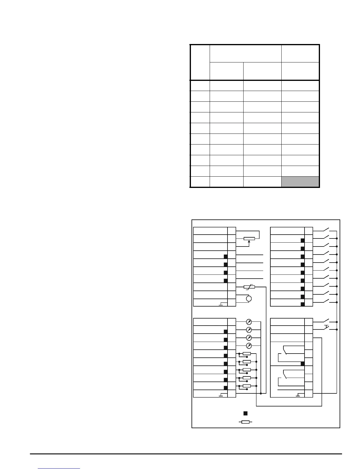
Figure 6-5 Control connections
Pin
Encoder
Serial
Comms.
Reference
PL4
Feedback
SK3/PL3* PL2
10V 0V 0Visolated
2 NC Supply /TX
3A A /RX
4/A /A NC
5B B NC
6/B /B TX
7NC NC RX
8C C NC
9/C /C NC
10 0V 0V (NOT SK3)
F1 Run
F2 Inch Rev.
F3 Inch Fwd.
F4 Run Rev.
F5 Run Fwd.
F6
F7
F8
F9
F10
21
22
23
24
25
26
27
28
29
30
Enable
Reset
+24V (200mA)
31
32
33
34
35
36
37
38
39
40
Current
DAC1
DAC2
DAC3
ST1
ST2
ST3
ST4
ST5
0V
11
12
13
14
15
16
17
18
19
20
+10V (5mA)
-10V (5mA)
Reference
GP1
GP2
GP3
GP4
Thermo
Tacho
0V
1
2
3
4
5
6
7
8
9
10
T
Drive
Healthy (Normal)
N/O
0V
TB4
TB3TB1
TB2