Mentor ll User Guide 21
Issue Number: 12 www.controltechniques.com
7.2 Setting Up to Run
Install the Drive and make electrical power and control connections in
accordance with Chapter 8 Parameter Set , and Figure 6-2, Figure 6-3
and Figure 6-4. Before attempting to run the Drive, there are further
connections and settings - some optional - to make or to be considered.
These are summarized below:
7.2.1 Link LK1 (Jumper) and Switches
The link LK1 (jumper) and switch block are located on PCB MDA2B
(Figure 6-4), accessible when the lower, snap-on front cover is removed
(Figure 6-1).
• ONE ONLY to be selected
7.2.2 Potentiometer RV1
Refer to Figure 6-4.
Pot. Purpose
RV1 Tachogenerator (tachometer) feedback adjustment
Procedure for Adjustment
1. Select the appropriate tachogenerator range using SW1.
2. Set LK1 in the ADJUST position.
3. Adjust RV1 until the value of parameter 03.02 (Speed Feedback) is:
where V
max
= Tach. voltage at full speed.
4. Set LK1 in the FEEDBACK position and fine tune RV1 with the
motor running at between half to three-quarter speed.
7.3 Getting Started
Essential data
Before attempting to tune a Mentor II to operate a particular load, collect
the following information from the nameplate of the motor,
manufacturers data, and other sources.
Data values are given here for the sake of the worked examples which
follow.
• Armature full load amps 67A
• Armature voltage 500V DC
• Field current 1.85A
• Field voltage 300VDC
• Base speed 1750rpm
• Maximum permissible speed with weakening field 2500rpm
• The method of delivering speed feedback data to the Drive - various
examples are considered below
Worked examples
7.3.1 Armature current
Current Limit
Current limit is set in parameter 04.05 only if the Drive is not
regenerative, and in both 04.05 and 04.06 if it is regenerative.
An M75 Drive is rated at 75A full load current.
The default value (1000) of parameter 04.05 (and 04.06)allowsa
maximum current limit of 150% of full load current, which would be 1.5 x
75 = 112.5A.
Full load current for the selected motor is 67A, and if its maximum
current limit is 150%, which is normal, the maximum current that it may
experience is 100.5A.
Accordingly, the Drive must be adjusted to correspond, or the motor will
be damaged. Calculate the ratio from :
The full-scale value of the Current Limit parameters, corresponding to
150% of full load current of the motor, is 1000. The actual setting of the
Current Limit parameters is, therefore :
1000 x 0.89 = 890
Set 04.05 =890.
If the Drive system is regenerative,
set 04.06 =890also.
Current resolution
The rating of the selected Drive is typically higher than the rating of
the motor, but it should not be very much higher. It would not be
prudent to select a Drive-to-motor ratio less than 2/3 (current limit
parameter setting 600).Current feedback resolution at any lower
ratio would be unable to give good current loop control.
Although full scale resolution can be achieved by
changing the burden resistors of the Drive current
transformer, this would create a non-standard Drive
that is not a stock item. The risk is that the Drive might
be replaced by a standard Drive of the same nominal
rating; the motor could be permanently damaged.
Special modifications of this nature should always be
supported by thorough documentation, and the non-
standard Drive should itself be indelibly tagged in
some way.
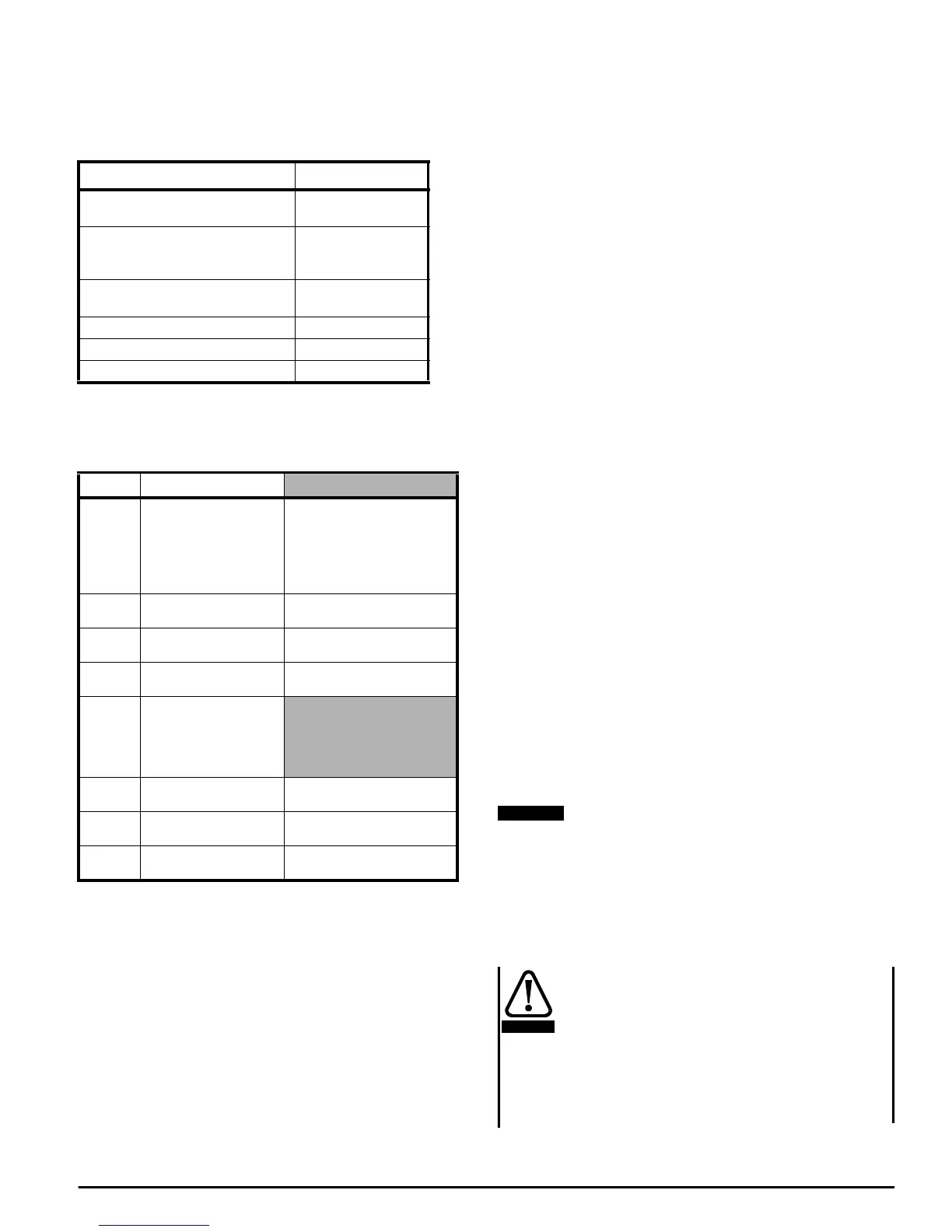
Action Reference
Preset the link (jumper)LK1 and
switches
7.2.1 below
Preset the adjustable potentiometer if
tachogenerator (tachometer)
feedback selected
7.2.2 below
Adjust operating parameters as
appropriate to the application
Section 8.1
Autotune current loop parameter 05.09
Adjust field feedback scaling parameter 06.11
Allocate security code optional Section 8.2
Control Purpose
SW1A
Logic input polarity.
MDA2Bis marked POS.
andNEG.toindicatethe
positions of SW1A.
Pos. = 24V
Neg. = 0V.
POWER-OFF BEFORE
CHANGING
SW1H 60V to 300V
Tachogenerator (tachometer)
feedback range*
SW1G 50V to 200V
Tachogenerator (tachometer)
feedback range*
SW1F 10V to 50V
Tachogenerator (tachometer)
feedback range*
LK1
Tachogenerator
(tachometer)
potentiometer
calibration adjustable
link (jumper)
SW1D +15V
Encoder supply voltage
selector*
SW1C +12V
Encoder supply voltage
selector*
SW1B +5V
Encoder supply voltage
selector*
03.02
10 000,
V
max
-------------------
=
MotorFullLoadCurrent
DriveRating
------------------------------------------------------------------------
67
75
------
0.89==
NOTE
CAUTION