Mentor ll User Guide 5
Issue Number: 12 www.controltechniques.com
4Data
4.1 Specifications
Maximum input voltage to Drive (L1, L2 and L3, i.e. main power to
thyristor bridge)
480V +10% standard
525V +10% optional
660V +10% special order
Maximum recommended motor voltage
Varm = 1.15 x Vsupply
Input power supply voltage (E1, E2 and E3, i.e. auxiliary power
supply)
Balanced 3-phase 3-wire, 45Hz to 62Hz, maximum 480V +10%.
With the higher voltage (525V, 660V) versions the maximum power
supply voltage is also 480V +10%.
The input to the control (electronic) circuits is:
Standard -2-wire, 220V - 10% to 480V +10%
With North American field bridge -3-wire, 220V - 10% to 480V +10%
E1 & E3 must be connected to the same phases as L1 & L3
Output supplies and references (Short-circuit proof)
10V reference ±5% 10mA Drive capability.
Encoder supply 300mA Drive capability at 5V, 12V or 15V selectable.
+24V supply 200mA Drive capability for relays.
All outputs are wire-proof - unaffected by accidental short circuiting.
Ambient temperature & humidity
Rated ambient temperature 40°C (104°F)
Rated maximum altitude 1000m (3200ft).
Storage temperature range -40°Cto+55°C (-40°Fto131°F)
Humidity requirement non-condensing.
Derating
Nominal ratings are affected by:
1. The altitude of the installation.
Where the site is above 1000m (3200ft), reduce the normal full load
current by 1.0% for each additional 100m (320ft), up to a maximum
of 4000m.
2. The ambient temperature.
Where the local ambient temperature is above 40°C(104°F), derate
by 1.5% per °Cupto55°C (0.75% per °Fupto131°F).
Enclosure Ingress Protection
Mentor II Drives are constructed in accordance with European IP00
specification. Mentor II Drives are suitable for mounting in NEMA
ingress-protected enclosures.
The Drive must be protected against moisture and conductive
contamination. The Drive is intended for use in pollution degree 2
environments.
4.2 Ratings
4.2.1 Current, input and output
Mentor is suitable in a circuit capable of delivering no
more than 10000 RMS symmetrical amperes for M25-
M210 and M25R-M210R and 18000 RMS symmetrical
amperes for M350-M825 and M350R-M825R short
circuit current, 480V +10% maximum.
• Motor rating may be increased at higher armature voltages
Refer to Maximum recommended motor voltage in section
4.1 Specifications .
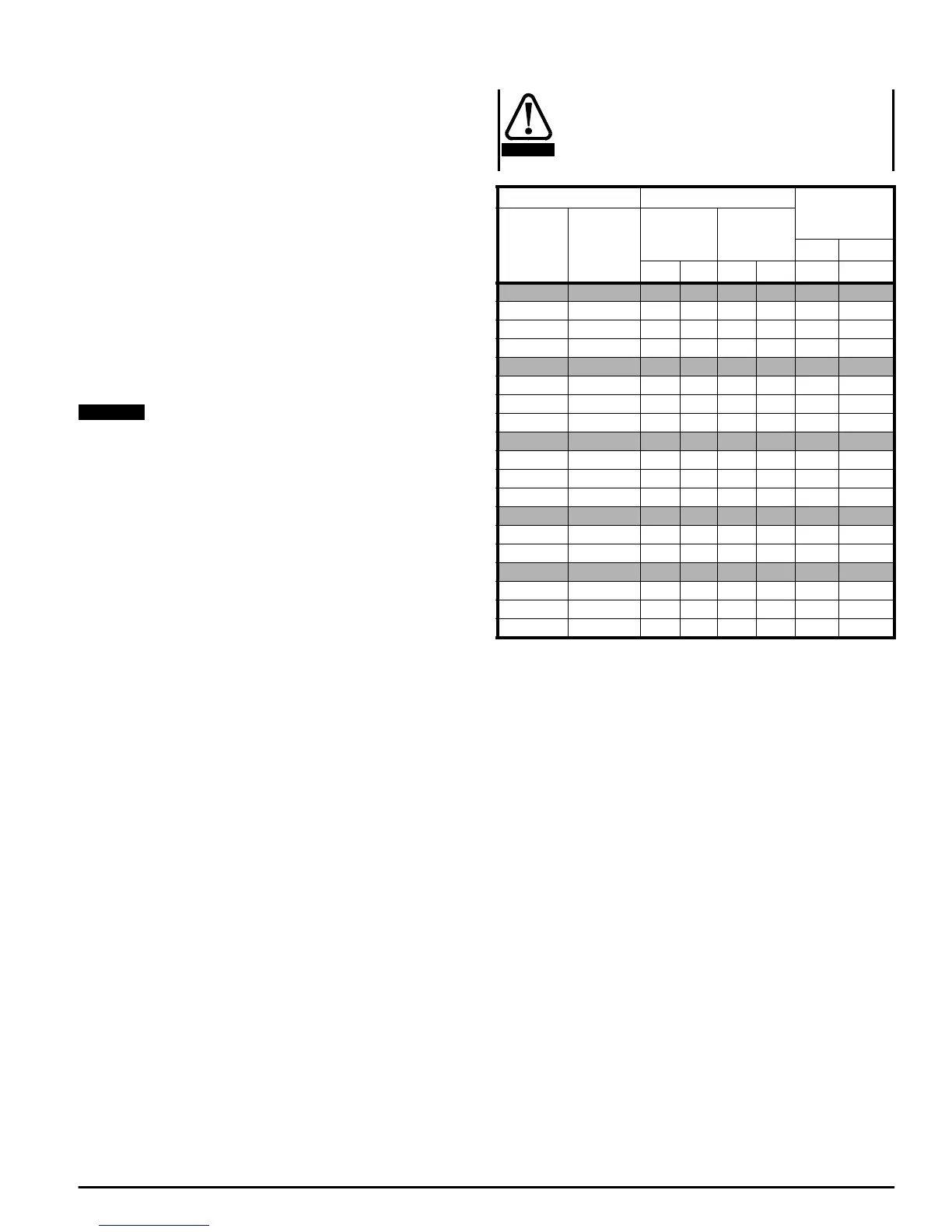
NOTE
Drive type & model Typical* ratings Maximum
continuous
current rating
Single
Quadrant
Four
Quadrant
at 400V
(armature)
at 500V
(armature)
input output
kW HP kW HP Aac Adc
M25 M25R 7.5 10 9 12 21 25
M45 M45R 1520192538 45
M75 M75R 3040385060 75
M105 M105R 37.5 50 47 63 88 105
M155 M155R 56 75 70 94 130 155
M210 M210R 75 100 94 126 175 210
M350 M350R 125 168 156 209 292 350
M420 M420R 150 201 188 252 350 420
M550 M550R 200 268 250 335 460 550
M700 M700R 250 335 313 420 585 700
M825 M825R 300 402 375 503 690 825
M900 M900R 340 456 425 570 750 900
M1200 M1200R 450 603 563 755 1000 1200
M1850 M1850R 750 1005 938 1258 1540 1850
CAUTION