58 Mentor ll User Guide
www.controltechniques.com Issue Number: 12
Menu 07: Analog Inputs & Outputs
Scaling parameters have a multiplying range from 0.001 to 1.999 (a
multiplier of zero would give the parameter a null value).
Source and Destination parameters define a parameter to be used as
either input or output, thereby defining the function of the programmable
input and output terminals.
Menu 07 contains three analog-input/output groupings. There are two
separate groups of analog input. The first is a 12-bit analog input which
is normally used as the speed reference input (refer to Menu 01,
Diagram B), but can alternatively be programmed to any real RW (but
not integer) destination.
High accuracy is achieved by voltage-to-frequency conversion. The
terminal can be programmed as a voltage input or as a current loop
input, with options 0-20mA, 20-0mA, 4-20mA or 20-4mA.
The second group provides a flexible means for scaling and assigning
destinations to the four general purpose inputs GP1, GP2, GP3 and
GP4, all of which are 10-bit resolution.
Finally, three analog outputs, via digital-to-analog (DAC) converters,
feature programmable-source parameters and scaling.
Displays the value of the analog signal applied to terminal TB1-04. Can
be used as a general-purpose input for monitoring, or for Processor 2
special applications.
Displays the value of the analog signal applied to terminal TB1-05. Can
be used as a general-purpose input for monitoring, or for Processor 2
special applications.
Displays the value of the analog signal applied to terminal TB1-06. Can
be used as a general-purpose input for monitoring, or for Processor 2
special applications.
Displays the value of the analog signal applied to terminal TB1-07. Can
be used as a general-purpose input for monitoring, or for Processor 2
special applications.
Displays the value of the analog speed demand at terminal TB1-03, or
master encoder (pulse tach.) reference via PL4, and after scaling by
07.24; dependent on reference mode being selected by 07.25.
Monitors the value of the voltage applied to line input terminals L1, L2,
L3 (the thyristor (SCR) stack supply).
Monitors the temperature of the thyristor (SCR) stack on those Drives
provided with thermistors.
Selects the source of analog output 1 via terminal TB2-12.
Selects the source of analog output 2 via terminal TB2-13.
Selects the source of analog output 3 via terminal TB2-14.
Of the following invisible parameters, Scaling parameters have a
multiplying range from 0.000 to 1.999
Source and Destination parameters define a parameter to be used
as either input or output, thereby defining the function of the
programmable input and output terminals.
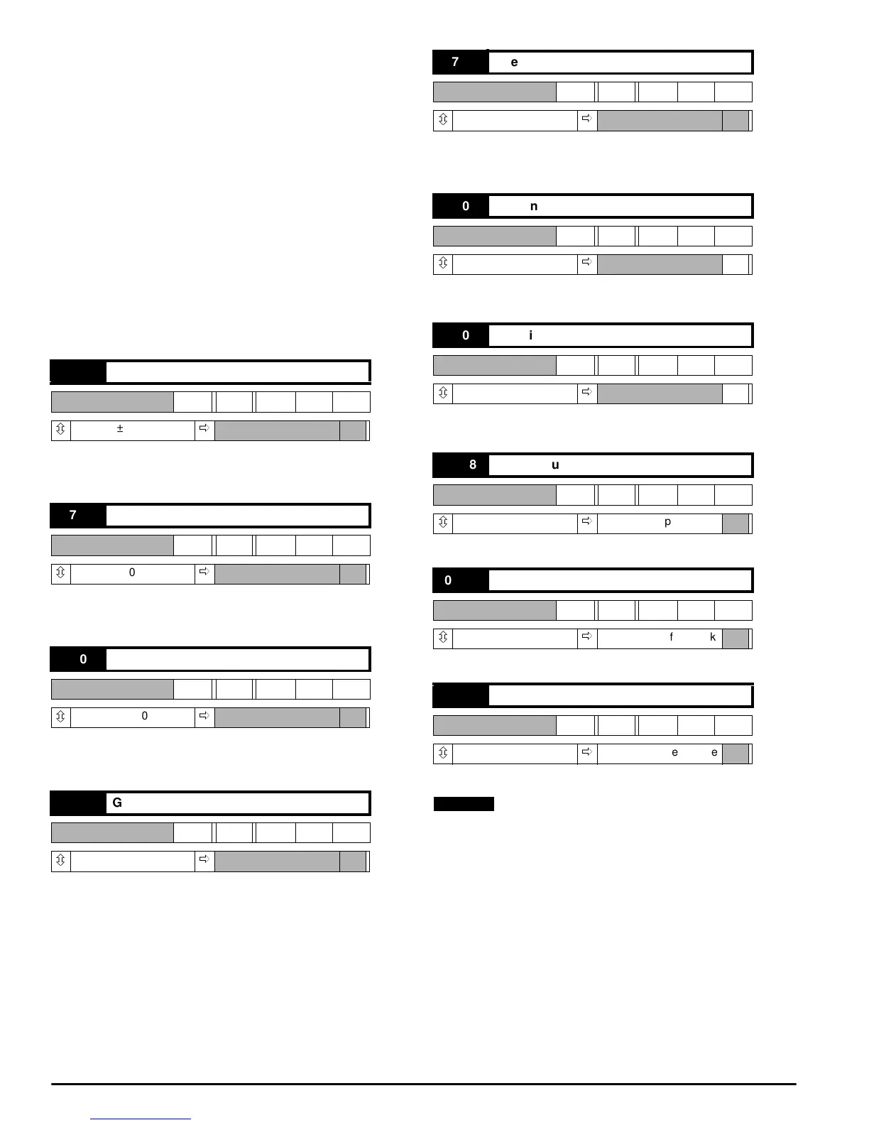
07.01 General purpose input 1
RO Bi
ô
±1000
ð
07.02 General purpose input 2
RO Bi
ô
±1000
ð
07.03 General purpose input 3
RO Bi
ô
±1000
ð
07.04 General purpose input 4
RO Bi
ô
±1000
ð
07.05 Speed reference input
RO Bi
ô
±1000
ð
07.06 RMS input voltage
RO Uni
ô
0 ~ 1000
ð
V
07.07 Heatsink temperature
RO Uni
ô
0 ~ 1000
ð
o
C
07.08 DAC 1 source
RW Uni
ô
0 ~ 1999
ð
+201, ramp output
07.09 DAC 2 source
RW Uni
ô
0 ~ 1999
ð
+302, speed feedback
07.10 DAC 3 source
RW Uni
ô
0 ~ 1999
ð
+304, armature voltage
NOTE