16 Mentor ll User Guide
www.controltechniques.com Issue Number: 12
6.2.2 Overvoltage suppression
The Mentor II Drive contains overvoltage suppression components to
protect the thyristors from high voltage pulses (transients or spikes)
appearing between the phases because of lightning strikes etc. It is also
designed to withstand pulses of over 4kV between the phases and
ground.
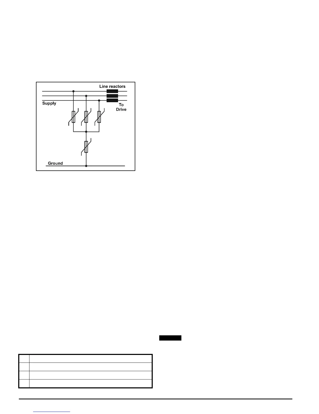
In regions of high lightning activity, especially where grounded delta
supplies are in use, it is recommended that additional protection should
be fitted externally between the phases and ground. This would typically
be by using MOVs (varistors).
One possible arrangement is shown in the diagram below:
The AC voltage rating of the MOVs can be up to 550V. This is suitable
for all supply voltages up to 660V +10%.
Ensure that the MOVs are rated for surge currents of at least 3kA for the
standard surge (1.2/50µs voltage or 8/20µs current). The wires to the
MOVs should be short (eg less than 6in/15cm) to avoid additional over-
voltage caused by wiring inductance with the fast-rising current.
MOVs approved by a safety agency such as UL are recommended, and
in some regions this is essential for legal or insurance reasons.
6.2.3 Overvoltage category and voltage surge
suppression
The Mentor II Drive contains comprehensive voltage surge suppression
and co-ordinated electrical spacings. It is resistant to surges of 4kV
between lines and from lines to ground.
The 480V version of the Drive may be connected to a supply system of
overvoltage category III (as specified in IEC664-1). This means that it is
suitable for permanent connection to any power system other than an
outdoor installation. For outdoor installation it is recommended that
additional overvoltage protection be provided.
The 525V and 660V versions may be connected to a supply system of
overvoltage category II. For permanent connection directly to industrial
supply systems it is necessary to provide additional surge suppression
between lines and ground. Suitable suppression devices using metal
oxide varistors (MOVs) are widely available. This is not required where
the Drive is provided with an isolation transformer.
The status relay contacts are designed for overvoltage category II at
240V.
Overvoltage categories are as follows:
6.3 Current Feedback Burden Resistors
To allow the use of a motor which has a lower rating than the Drive, the
current feedback has to be re-scaled by changing the burden resistors
R234 and R235 (or in the case of Drive size M350 and above, the three
resistors R234, R235 and R236) mounted on the power board. The
following equations provide the value of the appropriate resistance.
Resistors are in parallel.
Where Imax is 150% of the rated full load current of the motor:
For Drives M25 up to M210R (up to 210A DC output) and PCBs
MDA75, MDA75R, MDA 210, and MDA210R:
For Drives M350 and above, and PCB MDA6, three burden
resistors, R234, R235 and R236 are used in parallel:
Worked Example of Current Feedback Burden Resistor Values
ForanM350Drive:
Full load current output (Table 1) is 350A
Maximum current is 350 x 1.5amps
Total burden resistance:
If R236 is given a high value, say 390Ω, then:
and:
From data tables of standard resistor values, find two which give the
closest approximation.
Forexample,if:
R234 = 5.6 Ω and R235 = 6.8 Ω,
then -
≈ 0.33076 Ω
The power rating of each burden resistor in turn is calculated from :
and where the voltage across the three resistors in parallel is 1.6V,
power absorbed is :
R234
a 0.5W or 0.6W rating is adequate
R235
a 0.5W rating is adequate
R236
a 0.25W rating is adequate
Ifthecurrentripplemeasuredatterminal11islessthan0.6Vp-p,it
is possible to increase the burden resistors (provided that version
V5.1.0 (or later) software is used) by a factor of 1.6. If the burden
resistors are increased parameter 05.29 must be set to 1.
The burden resistor values should not be increased by the factor of
1.6 if the current ripple measured at terminal 11 is greater than 0.6V
as the Drive will operate better with the standard values.
I Protected circuits with overvoltage surge suppression
II General building power supplies for use by electrical appliances
III Fixed installations with permanent supply connection
IV Building power incomer (eg utility meter etc.)
Overvoltage Suppression
Rtotal
400
I
max
-----------
=
Rtotal
1600
I
max
-------------
=
Rtotal
1600
350 1.5×
------------------------
3Ω==
1
Rtotal
-------------------
1
R234
--------------
1
R235
--------------
1
R236
--------------
++=
1
3
---
1
390
---- --- ---
–
1
R234
--------------
1
R235
---- --- ---- ---
+=
1
R234
---- ---- --- ---
1
R235
--------------
– 0.33076Ω=
1
5.6
--------
1
6.8
--------
– 0.33076Ω=
Power W()
V
2
R
--- ---
=
1.6
2
5.6
---- ---- ---
0.456W=
1.6
2
6.8
---- ---- ---
0.376W=
1.6
2
390
---- ---- ---
6mW=
NOTE