66 Mentor ll User Guide
www.controltechniques.com Issue Number: 12
Menu 10: Status Logic & Diagnostic Information
All real (not bit) RO parameters are frozen at the instant of tripping as an
aid to diagnosis of the fault. They remain in this condition until the Drive
is reset.
0 = Drive stationary or running in reverse
1 = Drive running forward at >zero speed threshold
Forward direction defined as follows:
When tachometer feedback selected, terminal TB1-09 negative with
respect to terminal TB1-10.
When armature voltage feedback selected, terminal A1 positive with
respect to terminal A2.
When encoder (pulse tach.) feedback selected, A-channel leads
B-channel.
0 = Drive stationary or running forward
1 = Drive running in reverse at >zero speedthreshold
Reverse direction defined as follows:
When tachometer feedback selected, terminal TB1-09 positive with
respect to terminal TB1-10.
When armature voltage feedback selected, terminal A1 negative
with respect to terminal A2.
When encoder (pulse tach.) feedback selected, A-channel lags
B-channel.
If 10.01 = 10.02 = 0, the motor is either stationary or running at
<zero speed threshold. In this condition, 10.09 = 1 and the Zero
Speed LED illuminates on the keypad (and RL2 is turned on, if
programmed to indicate zero speed).
0 = Drive not in current limit
1 = Drive in current limit
Indicates that the sum of the current demand 04.01 and the offset 04.09
is being limited by the current limit over-ride 04.03 or by one of the
bridge limits.
0 = disabled
1 = enabled
Indicates that thyristor (SCR) bridge 1 (the forward or positive bridge) is
being fired. Does not necessarily indicate that the bridge is conducting,
since conduction depends on firing angle and operating conditions.
0 = disabled
1 = enabled
Indicates that thyristor (SCR) bridge 2 (the reverse or negative bridge) is
being fired. Does not necessarily indicate that the bridge is conducting,
since conduction depends on firing angle and operating conditions.
0 = firing pulses not phased back
1 = firing pulses phased back (at standstill)
Indicates that the firing pulses are being phased back by the action of
the standstill function. Refer to 05.18 and 05.19.
0 = Drive not at speed
1=Driveatspeed
Indicates that the Drive has attained set speed, post-ramp reference
02.01 = pre-ramp reference 01.03, and also that comparison of final
speed demand 03.01 with speed feedback 03.02 results in a speed error
of <1.5% of maximum speed. External signal also provided through
open collector output ST2 to terminal TB2-16 if source parameter 09.13
is at default setting.
0 = motor not overspeeding
1=motoroverspeed
Indicates that the speed feedback 03.02 > 1000, that is, the speed is out
of range, suggesting that the motor is being mechanically driven faster
than the maximum speed of the Drive. This function is a monitor only,
anddoesnotinitiateatripsignal.
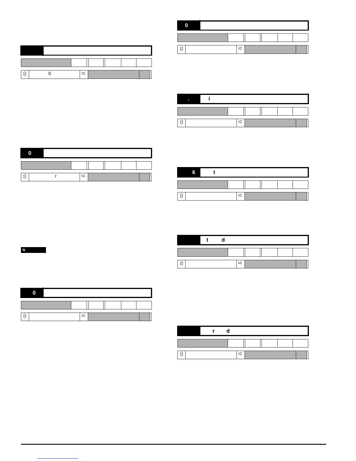
10.01 Forward velocity
RO Bit
ô
0or1
ð
10.02 Reverse velocity
RO Bit
ô
0or1
ð
10.03 Current limit
RO Bit
ô
0or1
ð
NOTE
10.04 Bridge 1 enabled
RO Bit
ô
0or1
ð
10.05 Bridge 2 enabled
RO Bit
ô
0or1
ð
10.06 Electrical phase-back
RO Bit
ô
0or1
ð
10.07 At speed
RO Bit
ô
0or1
ð
10.08 Overspeed
RO Bit
ô
0or1
ð