92 Mentor ll User Guide
www.controltechniques.com Issue Number: 12
10 Serial Communications
The control circuits are isolated from the power circuits
in the Drive by basic insulation only. The installer must
ensure that the external control circuits are insulated
from human contact by at least one layer of insulation
rated for use at the AC supply voltage.
If the control circuits are to be connected to other
circuits classified as Safety Extra Low Voltage (SELV)
(e.g. to a personal computer), an additional isolating
barrier must be included in order to maintain the SELV
classification.
A communications interface is standard in all Mentor II Drives. It is a
machine-machine interface, enabling one or more Drives to be used in
systems controlled by a host such as a process logic controller (PLC) or
computer.
Mentor II Drives can be directly controlled, their operating configuration
can be altered, and their status can be interrogated by such a host, and
continuously monitored by data logging equipment.
The communication port of the Drive unit is the connector PL2 (Figure
6-4 on page 17). The standard connection is the RS422.
Protocol is ANSI x 3.28 - 2.5 - A4, as standard for industrial interfaces.
Connections
The serial communications interface is made available on the 9-Way D-
Type connector labelled PL2 on the MDA2B card. This connector
provides standard RS422 interfacing.
The Mentor Drive is equivalent to two-unit loads, therefore up to 15
Drives may be connected to a host controller before the use of repeaters
is necessary. When repeaters are used, up to 99 Drives may be
connected.
RS422ispracticallythesameasRS485,themaindifferencebeing
RS485 allows more than one master controller.
An RS232 connection may be made to the RS422 port,
but is not recommended for any purpose other than
commissioning due to its inferior specification (low
noise rejection, limited cable length, etc). Note that
RS232isnotthesameas2-wireRS422/485.
Connecting to the Drive
485 serial communications port
MentorSoft connects to the RS485 Mentor II port by using either a
standard 4-wire RS232 to RS485 converter, or by fabricating the
following lead:
If you have problems...
Cannot go on-line:
Check connections to Drive.
Perform an auto-baud detection.
Make sure that the correct “COM” port is selected.
Ensure that the Mentor II is in 4-wire ANSI mode (11.13 =1).
The components of all messages between the host and a Mentor II Drive
are formed of ASCII characters. The format of a message, i.e. the
sequence in which the characters appear, is standardized for messages
of each different kind, and is explained under Structure of Messages,
below.
Preliminary Adjustments to the Drive
Each Drive requires a unique identity number, or serial address, set by
parameter 11.11.TheBaudrate11.12 is required to be set to match the
host. Data, Drive status and the parameter set-up can be read from the
Drive in any mode, provided only that the Drive is powered up, and that
the serial address and Baud rate are correctly set.
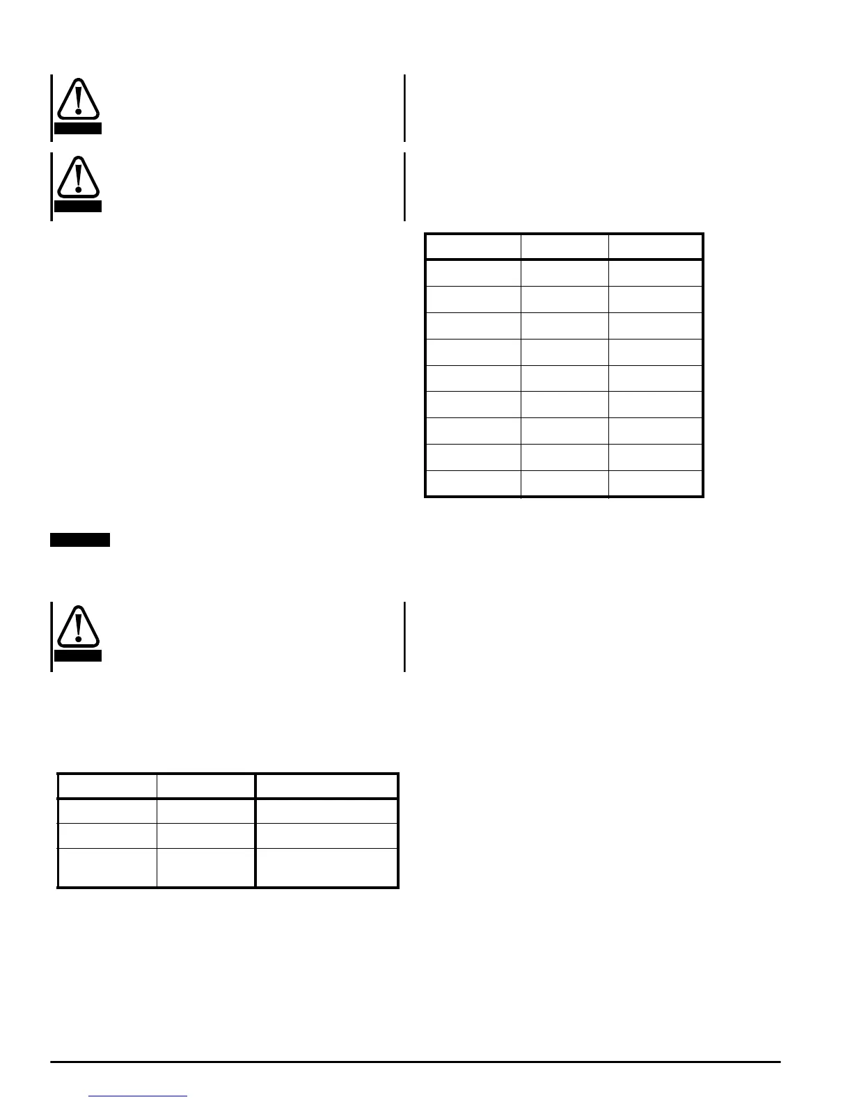
The following tables gives the terminal designations for the connector
PL2 for both RS422 and RS232 communications links
Routing the serial communications cable
A data communications cable should not run parallel to any power
cables, especially ones that connect Drives to motors. If parallel runs are
unavoidable, ensure a minimum spacing of 300mm (1 foot) between the
communications cable and the power cable.
Cables crossing one another at right-angles are unlikely to give trouble.
The maximum cable length of a RS422 link is approximately 1,000
meters (4,000 feet)
Termination
When a multi-drop RS422 network is used, it is necessary to connect a
120Ω resistor between the two receive lines of the last unit on the bus
(i.e. the unit farthest away from the host). Care must be taken to ensure
that other units in the network do not have the resistor already fitted -
excessive signal loss will occur otherwise. The termination resistor can
be fitted between the two posts labelled R6 to the right of the 9-way D-
Type connector.
Components of messages
Control Characters
To conform to the standard structure of a message, the stages of a
message are signalled by control characters. Each character has a
specific meaning, a standard abbreviation, and is transmitted and
received in ASCII code. If a message is initiated from a keyboard, the
control characters are keyed by holding the Control key down while
making a single-letter keystroke. Of the 32 control characters in the
ASCII set, the seven in the following table are used in Mentor II serial
communications.
PC 25-way PC 9-way PL2 9-way
32 2
23 3
7 5 1+6+7
(link all three terminals)
WARNING
WARNING
NOTE
CAUTION
Pin no. RS232 RS422
1NC0V
2TXDTXD
3RXDRXD
4
5
60VTXD
70VRXD
8
9