Mentor ll User Guide 73
Issue Number: 12 www.controltechniques.com
Menu 13: Digital Lock
Indicates the difference between the positions of the master shaft and
the slave shaft.
See also 13.07, 13.12 and 13.13
See also 13.06, 13.12 and 13.13
Parameters 13.06 and 13.07 are used, in conjunction with each other, to
define a 16-bit velocity reference when parameter 13.12 =0.
Parameter 13.06 is the least-significant component.
Parameter 13.07 is the most-significant component.
Each unit of 13.07 represents 256 increments of 13.06.
Determines the amount of velocity correction per unit of position error.
The setting thus determines how quickly the loop responds to a
disturbance, and thus affects the motor output shaft position.
Thegainapplied
This parameter must be adjusted in conjunction with the Speed Loop
PID Gains 03.09, 03.10 and 03.11 to attain the best balance between
stability and quick response.
Limits the amount of the velocity-correction resulting from a position
error.
0 = disabled
1 = enabled
Enables the Position Loop software.
0 = disabled
1 = enabled
When 13.11 = 1, the position error, relative to the time the position loop
is closed, is always absolute. This means that if the slave output shaft is
slowed down by an overload, position will be regained by an automatic
speed increase when the load reduces to or below maximum.
When 13.11 = 0 (default), the Position Loop is closed only when the At
Speed condition is reached. This allows the accelerating Ramps to be
used without overspeeding the slave output shaft.
1 = master encoder (pulse tach.)
0 = precision reference
Determines the source of the digital loop reference, as between the
master encoder (pulse tach.) (13.01) or the precision references (13.06
and 13.07).
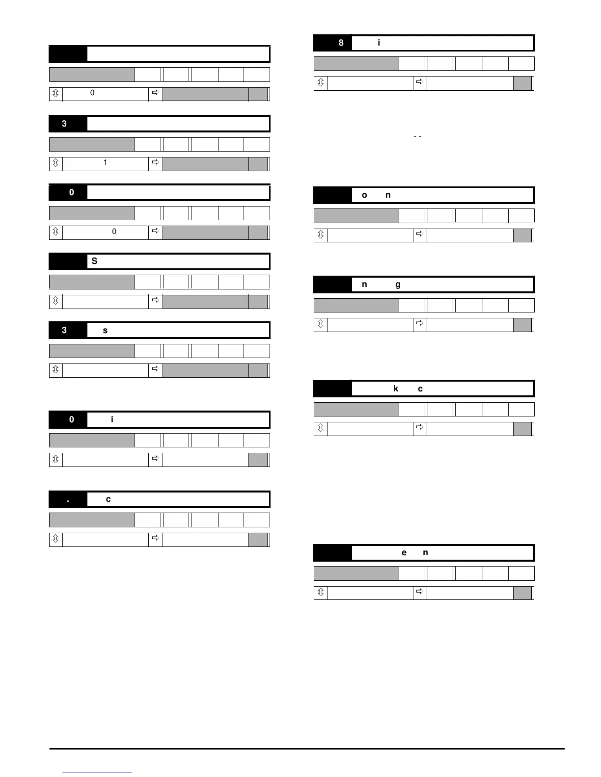
13.01 Master encoder counter
RO Uni
ô
0 ~ 1023
ð
13.02 Slave encoder counter
RO Uni
ô
0 ~ 1023
ð
13.03 Master counter increment
RO Bi
ô
±1000
ð
13.04 Slave counter increment
RO Bi
ô
±1000
ð
13.05 Position error
RO Bi
ô
±1000
ð
13.06 Precision reference (Isb)
RW Uni
ô
0~255
ð
000
13.07 Precision reference (msb)
RW Uni
ô
0~255
ð
000
13.08 Position loop gain
RW Uni
ô
0~255
ð
025
13.09 Position loop correction limit
RW Uni
ô
0 ~ 1000
ð
+010
13.10 Enable digital lock
RW Bit
ô
0or1
ð
0
13.11 Rigid lock selector
RW Bit
ô
0or1
ð
0
13.12 Precision reference source
RW Bit
ô
0or1
ð
0
13.08
256
---------------
=