4 Mentor ll User Guide
www.controltechniques.com Issue Number: 12
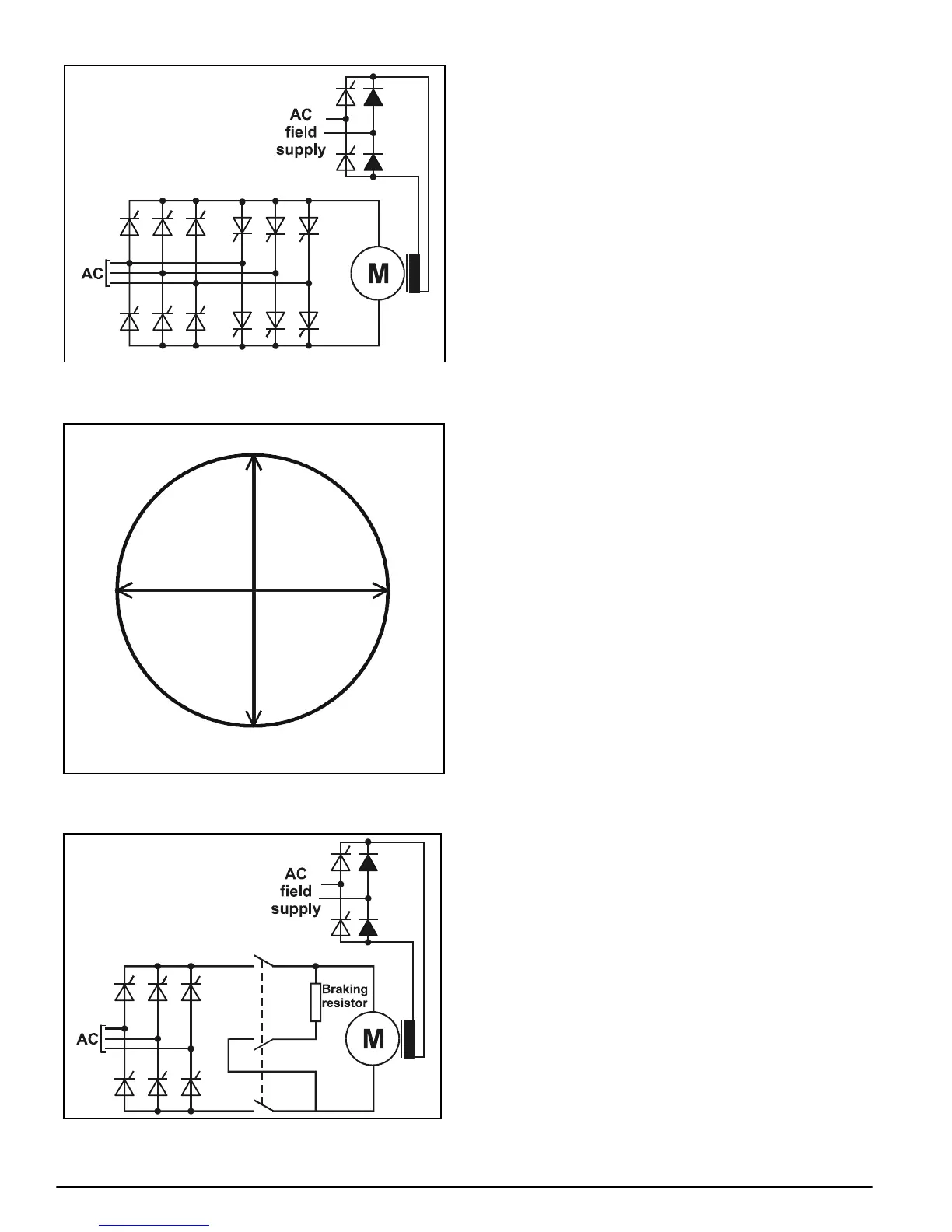
Figure 3-3 Dual bridge or parallel-pair 3-phase thyristor (SCR)
arrangement for a 4-quadrant DC motor drive
Figure 3-4 The four quadrants of the DC motor torque-speed
diagram
Figure 3-5 Typical arrangement for dynamic (resistive) braking of a
“single-ended” DC drive
3.4 Control
Regardless of whether a Drive is single- or four-quadrant, motor
response is fundamentally a function of voltage output, which is a
function of the firing angle of the thyristor (SCR) bridge, and this can be
controlled precisely.
The quality of the response obtained from the motor is, therefore,
dependent on the ability of the Drive logic to receive, interpret and
process a complete range of data concerning the state of the motor, and
the desired state. Some of this data may be from external sources, such
as the speed reference (demand), torque reference, motor speed feed-
back, and so on; some are derived internally by the Drive logic itself, for
example, output voltage and current, and the demand condition of the
logic system at various stages.
The logic system requires a set of instructions to allow it to undertake the
process of interrogation, processing and signal-generation to control
thyristor (SCR) firing. The instructions are provided in the form of data
broken down into individual values or parameters for the user to provide
in accordance with the particular operations required for the motor
application. The behavior of the Drive in terms of any given industrial
application is a function of the information it receives for processing from
user-written and internally-monitored parameter values.
For this reason, the Mentor II Drive is equipped with a dedicated
microprocessor, and with software which is configured by the
parameters written to it by the user. The parameters cover every
significant factor related to motor performance, so that the user can set
the Drive up to meet the application requirements exactly. Further
parameters are provided for communications, security and other
operational functions.
3.5 Menus
The number of parameters is large, but understanding of them and
access to them have been greatly facilitated by arranging them in
menus, each menu covering a particular logical or functional grouping.
An overview of the control logic system of the Drive and a graphical
representation of each individual menu will be found in the set of logic
diagrams at the end of Chapter 8 Parameter Set .
3.6 Serial Communications
The serial communications link (interface) with which the Mentor II Drive
is equipped is a significant feature in relation to operation within an
industrial process application. For example, external programmable
process logic controllers (PLCs) can be set up with access to the whole
or part of the Drive logic, enabling the setting of parameters to be
changed, virtually instantaneously, to suit different stages of a duty cycle
or different operating conditions in the process.
The serial communications facility also provides for the operation of the
Drive to be continuously monitored for control or analytical purposes.
1
FORWARD
DRIVE
I = Current
M = Torque
V=Voltage(emf)
n = Speed
2
REVERSE
BRAKING
REVERSE
DRIVE
3
FORWARD
BRAKING
4
+M, +I
-n, -V +n, +V
-M, -I