Mentor ll User Guide 13
Issue Number: 12 www.controltechniques.com
6 Electrical Installation
6.1 Installation Criteria
6.1.1 Safety
The voltages present in the supply cables, the output
cables and terminals, the control power supply wiring
and in certain internal parts of the Drive are capable of
causingsevereelectricshockandmaybelethal.
Electric Shock Risk!
Whenever the Drive has been connected to the main
AC supply system it must be DISCONNECTED and
ISOLATED before any work is done that requires the
removal of a cover. A period of 2 minutes MUST elapse
after isolation to allow the internal capacitors to
discharge fully. Until the discharge period has passed,
dangerous voltages may be present within the module.
Persons supervising and performing electrical
installation or maintenance must be suitably-qualified
and competent in these duties, and should be given the
opportunity to study, and to discuss if necessary, this
Users Guide before work is started.
Ingress Protection
The Drive enclosure conforms to international
enclosure specification IP00 and is suitable for
mounting in NEMA-rated enclosures. It is necessary to
consider the location of and access to the Drive unit
itself in the light of local safety regulations applicable
to the type of installation.
6.1.2 Hazardous areas
The application of variable speed Drives of all types
may invalidate the hazardous area certification
(Apparatus Group and/or Temperature Class) of Ex-
protected (externally-protected) motors. Approval and
certification should be obtained for the complete
installation of motor and Drive. (Refer also to section
5.2.1 Location on page 8)
6.1.3 Earthing (Grounding)
Safety
Drives with isolated heat sinks require that the heat
sink is earthed (grounded) for safety. (Refer also to
section 5.2 Mounting on page 8)
It is recommended that any metal components which
could accidentally become live are solidly earthed
(grounded).
Earth (ground) impedance must conform to the
requirements of local industrial safety regulations and
should be inspected and tested at appropriate and
regular intervals.
6.1.4 Control System Earthing (Grounding)
External AC control circuits, for example, contactors, should be supplied
(from any two phases of the supply) through an isolating transformer
equipped with an earthing (grounding) shield (screen) between the
primary and secondary as shown in Figure 6-2 and Figure 6-3. The
controlwiringshouldbeconnectedtothesameearthing(grounding)
point if possible, or arrangements made to ensure that the earth
(ground) loop impedance complies with an authorized code of practice.
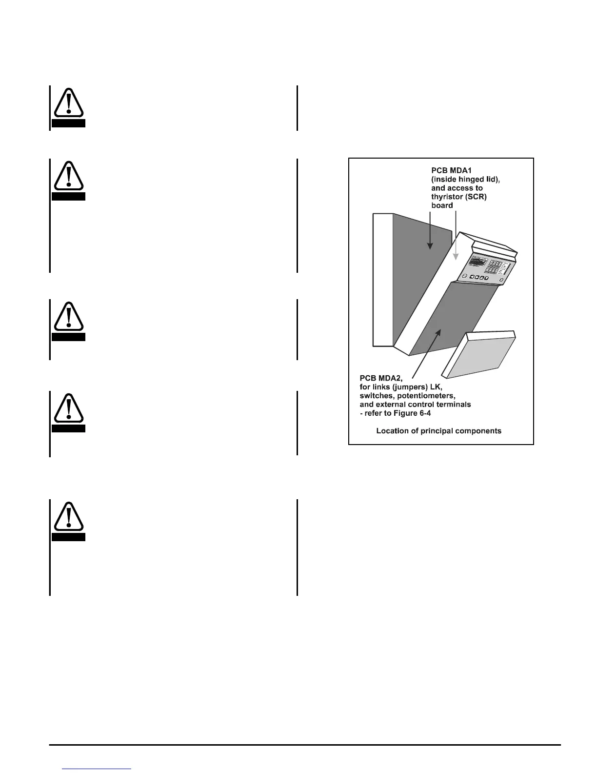
6.1.5 Location
The location of principal components is shown in Figure 6-1.
Figure 6-1
WARNING
WARNING
CAUTION
WARNING
WARNING