8 Mentor ll User Guide
www.controltechniques.com Issue Number: 12
5 Mechanical Installation
5.1 Dimensions
Principal dimensions are shown in Figure 5-3, Figure 5-4 and Figure 5-5.
Cut-out and drilling dimensions for mounting a Drive with the heatsink
projecting through a panel into the space behind are shown in Figure 5-3
and Figure 5-4.
5.2 Mounting
The Drive enclosure conforms to international enclosure specification
IP00 and is suitable for mounting in NEMA-rated enclosures.
5.2.1 Location
The Drive should be installed in a place free from dust, corrosive vapors
and gases, and all liquids. Care must also be taken to avoid
condensation of vaporized liquids, including atmospheric moisture.
Mounting arrangements & ventilation
If the Drive is to be located where condensation is likely to occur when it
is not in use, a suitable anti-condensation heater must be installed. The
heater must be switched OFF when the Drive is turned on. An automatic
changeover switching arrangement is recommended.
Mentor II Drives are not to be installed in classified Hazardous Areas
unless correctly mounted in an approved enclosure and certified.
(Refer also to Section 6.1.2, Hazardous Areas.)
5.2.2 Mounting and Cooling
There are certain variations across the Mentor II range of Drives, in
respect of mounting and cooling arrangements. With most models there
is the option of surface or through-panel mounting. The higher-rated
Drives require forced ventilation and can optionally be supplied complete
with ducted cooling fans.
Alternatively, the installer may arrange to use separately-provided
ducted cooling air. Air flow requirements are shown in Table 3. The
variants are summarized in the following table.
• Isolated heat sinks must be earthed (grounded) for safety.
A terminal is provided.
1. Surface-mounting requires the optional fan ducting, with integral
fans, mounting flanges and earthing (grounding) stud.
2. Adequate forced ventilation must be provided.
3. Asuitablefancanbesuppliedasanoptionalextra.
4. Enclosed.
5.3 Cooling and Ventilation
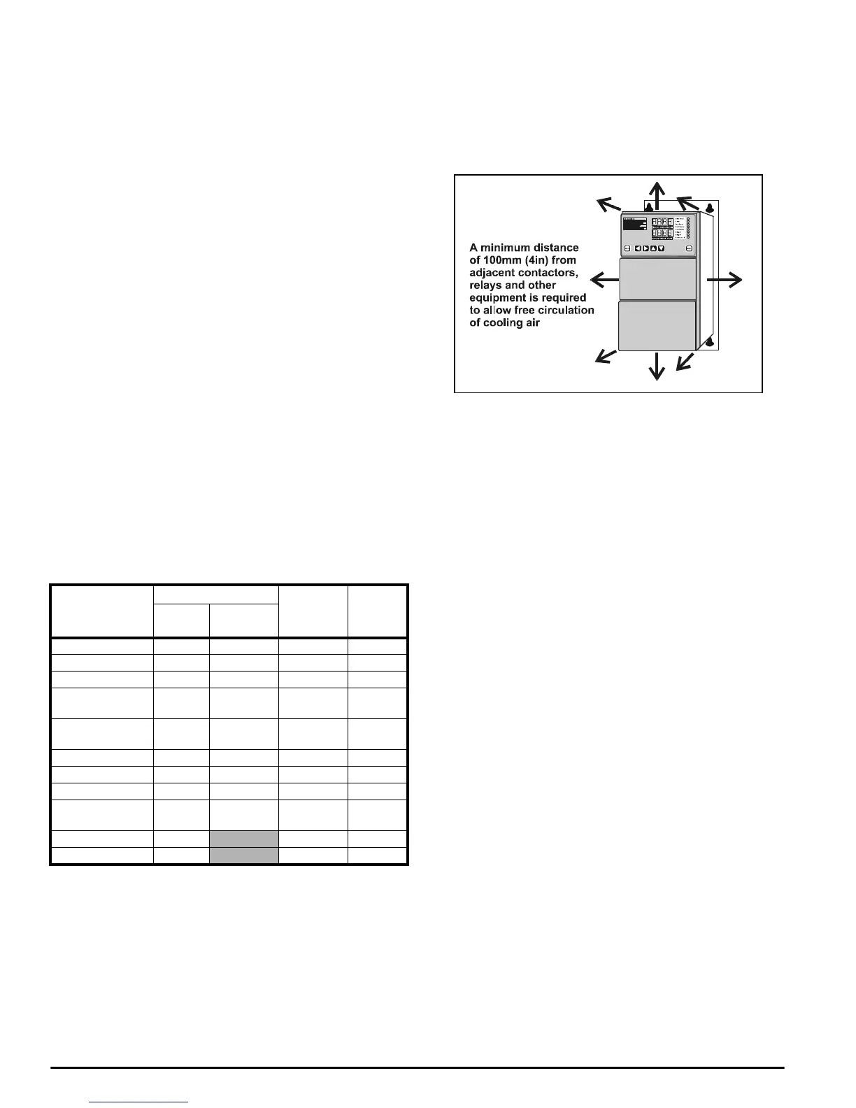
5.3.1 Enclosure minimum dimensions
Care must be taken that the enclosure in which the Drive is installed is of
adequate size to dissipate the heat generated by the Drive. A minimum
clearance of 100mm (4in) all around the Drive is essential, Figure 5-1.
All equipment in the enclosure must be taken into account in calculating
the internal temperature.
Figure 5-1
5.3.2 Effective heat-conducting area
The required surface area A
e
for an enclosure containing equipment
which generates heat is calculated from the following equation:
where
A
e
Effective heat-conducting area, in m
2
, equal to the sum of
the areas of the surfaces which are not in contact with any
other surface.
P Power loss of all heat-producing equipment in Watts.
T
i
Max. permissible operating temperature of the Drive in
o
C.
T
amb
Maximum external ambient temperature in
o
C.
k Heat transmission coefficient of the material from which the
enclosure is made in W/m
2
/
o
C.
Example:
Calculation of the size of an IP54 (NEMA 12) enclosure for a Drive
size M210
The worst case is taken as the basis of the example, for which the
following conditions are assumed:
• The installation is to conform to IP54 (NEMA 12), which means that
the Drive and its heatsink are to be mounted wholly within the
enclosure, and that the enclosure is virtually sealed and without any
ventilation of the air inside. Heat can escape only by conduction
through the skin of the enclosure, which is cooled by conduction,
convection and radiation to the external air.
• The enclosure is to stand on the floor and against a wall, so that its
base and back surfaces cannot be considered to play any part in the
cooling process.The effective heat-conducting area A
e
is provided
by the top, front, and two sides only, Figure 5-2.
• The enclosure is to be made of 2mm (0.1in) sheet steel, painted.
• The maximum ambient temperature is 25
o
C.
Drive model
Mounting
Ventilation Heat Sink
Surface
Through-
panel
M25toM75 Yes Yes Natural Isolated*
M25R to M75R Yes Yes Natural Isolated*
M105 and M105R Yes Yes Natural Isolated*
M155 and M155R Yes Yes
Forced (fan
built in)
Isolated*
M210 and M210R Yes Yes
Forced (fan
built in)
Isolated*
M350 to M550 Yes (1) Yes (2) Forced LIVE
M350R to M550R Yes (1) Yes (2) Forced LIVE
M700 and M825 Yes (1) Yes (2) Forced LIVE
M700R and
M825R
Yes (1) Yes (2) Forced LIVE
M900 to M1850 Only
Forced (3) LIVE (4)
M900R to M1850R Only
Forced (3) LIVE (4)
A
e
P
kT
i
T
amb
–()
---------------------------------
=