Mentor ll User Guide 51
Issue Number: 12 www.controltechniques.com
Menu 05: Current Loop
This is the final stage in the processing of the speed and torque
references and feedbacks to determine the final firing angle signal. The
normal principal input is the final current demand, which is subject to the
slew rate limit, summed algebraically with the current feedback and
further modified by whatever settings may have been applied to the
group of Current Loop parameters.
Current feedback, after scaling, delivers a readable signal to display
actual current in amps. Current feedback also is an important function in
the protection of the Drive. The feedback signal is monitored in relation
to the selected overload threshold, modified according to
preprogrammed values for overload time. The provision of two
parameters for overload timing allows settings to be applied so as to
take account of the fact that the cooling time of a motor can be longer
than its heating time.
For the Drive to operate the current ripple measured at terminal 11 which
is a voltage signal indicating current feedback, must be a minimum of
0.6V when there is no back emf i.e at zero speed.The current level
measured at the point of continuous conduction with this level of ripple is
9.2% of the Drive rating. With software version V5 (or later), software
parameter 05.29 allows the user to increase the current feedback
burden by a factor of 1.6. The software scales the current feedback
differently to compensate for the change in burden value. When 05.29 is
set and the burdens have been changed, the minimum vale of ripple
occurs at 5.7% of the Drive rating. The burdens should not be changed if
the ripple at terminal is greater than 0.6V.
The current feedback signal is derived from internal current
transformers. It is used for closed-loop control and indication of the
armature current, and to initiate motor protection.
The current feedback signal, modified by the scaling factor, becomes
available as an indication in amps. Refer also to 05.05.
This is the output of the current loop algorithm, and the input reference
totheASIC,whichgeneratesthefiringpulses.05.03 = 1023 indicates
fully phased forward.
This parameter limits the maximum rate of change of current demand.
Older types of motor, especially if of non-laminated construction, may
have a tendency to flash over if the rate of change of current is too high
for the inherent lag of the interpole windings.
Defined as:
Where:
S =slewrateinampss
-1
f = frequency of the power supply in Hz
I
max
= max. current (A)
To restrict the rate of change of current, parameter 05.04 should be
reduced.
The maximum output current, in amps, is scaled by this parameter. This
does not have any effect on the motor protection. The setting for05.05 is
calculated as follows:
05.05 =ifI
max
>1999A
05.05 = I
max
if 200A < I
max
<1999A
05.05 = I
max
x10ifI
max
<200A
Sets the threshold of armature current feedback beyond which the
current-time overload protection begins to integrate.
To disable the overload trip, parameter 05.07 and 05.08 should be
set to 0.
Integrating time for 05.06. For use in conjunction with 05.08, such that
05.07 < 05.08.
Timettotripis:
ReferalsotoMenu10,parameter10.18.
To disable the overload trip, parameter 05.07 and 05.08 should be
set to 0.
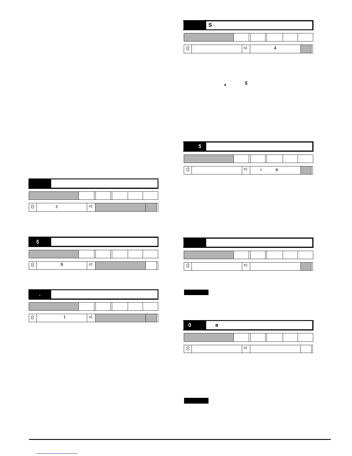
05.01 Current feedback
RO Bi
ô
±1000
ð
05.02 Current feedback (amps)
R0 Bi
ô
±1999
ð
A
05.03 Firing angle
RO Uni
ô
277 ~ 1023
ð
05.04 Slew rate limit
RW Uni
ô
0~255
ð
040
05.05 Maximum current (scaling)
RW Uni
ô
0 ~ 1999
ð
Drive current rating
05.06 Overload threshold
RW Uni
ô
0 ~ 1000
ð
+700
05.07 Overload integrating time (heating)
RW Uni
ô
0~255
ð
030 S
S
I
max
6f× 05.04×
256
---------------------------------------------
=
I
max
10
---- ---- ---
NOTE
t05.07()
1000 05.06()–
05.01()05.06()–
---------------------------------------------
×=
NOTE