20 Mentor ll User Guide
www.controltechniques.com Issue Number: 12
7 Operating Procedures
7.1 Keypad and Displays
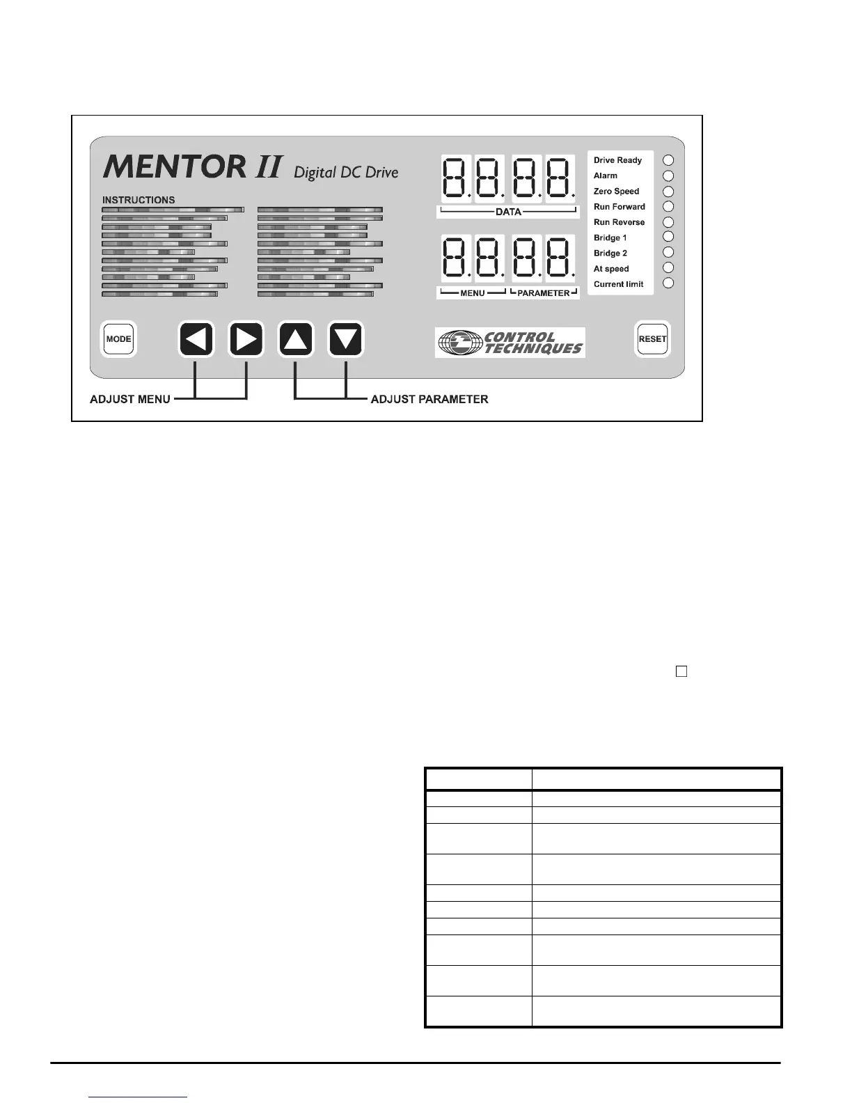
Figure 7-1 Keypad
The keypad serves two purposes:
1. It allows the operator to configure the Drive to match particular
applications and to change its behavior in a variety of ways, for
example by altering the times of acceleration and deceleration,
presetting levels of protection, and so on.
Subject to safety considerations, adjustments may be made with the
Drive running or stopped. If running, the Drive will respond
immediately to the new setting.
2. It provides full information about the settings and the operational
status of the Drive, and extensive diagnostic information if the Drive
trips.
For parameter adjustment, the keypad has five keys, Figure 8-1. Use the
LEFT or RIGHT keys to select a Menu (functional group of parameters).
The menu number appears to the left of the decimal point in the Index
window.
Use the UP or DOWN keys to select a Parameter from the chosen
menu. The parameter number appears to the right of the decimal point in
the Index window, and the value of the chosen parameter appears in the
Data window.
Press the MODE key once to access the displayed parameter value for
adjustment. The value flashes if access is permitted.
Use the UP or DOWN keys to adjust the value. To adjust rapidly, press
andholdakey.
Press the MODE key again to exit from the adjustment mode.
Store (make permanently effective) parameter values after changes,
otherwise the new values will be lost when the Drive is powered-off. To
store, set Parameter 00 = 1 and press RESET.
DISPLAYS
1. Index
The lower four-digit display indicates menu number to the left of the
(permanent) decimal point, and parameter number to the right.
2. Data
The upper four-digit display indicates the value of a selected
parameter. The present value of each parameter in turn appears in
the data display as parameter numbers are changed.
Numerical parameters have values in ranges of 000 to 255, 000 to
+1999, or 000 to 1000. Refer to Chapter 6 for parameter unit values,
e.g. volts, rpm, etc.
Bit parameter values are displayed as 0 or 1, preceded by a b. The
first digit for integer parameters (0 to 255) is a
?
.
3. Status Indicators
Nine LED’s to the right of the parameter data and index panels
present information, continuously updated, about the running
condition of the Drive and enable basic information to be seen at a
glance.
LED Illuminated Information
Drive ready The Drive is switched on and is not tripped
Drive ready flashing The Drive is tripped
Alarm flashing
The Drive is in an overload trip condition or is
integrating in the I x t region
Zero speed
Motor speed < zero speed threshold
(programmable)
Run forward Motor running forward
Run reverse Motor running in reverse
Bridge 1 Output bridge 1 is enabled
Bridge 2
Output bridge 2 is enabled
(Inactivein1-quadDrives)
At speed
Motor running at the speed demanded by the
speed reference
Current limit
Drive running and delivering maximum permitted
current