44 Mentor ll User Guide
www.controltechniques.com Issue Number: 12
Menu 03: Feedback Selection and Speed Loop
The principal inputs are the post-ramp reference 02.01 and the hard
speed reference 03.18. The post-ramp reference can be summed with or
replaced by the hard speed reference. The speed reference can,
alternatively, be the hard speed reference alone. The selected input can
be modified by the addition of an offset. The result of this summation is
the final speed demand (03.01) which is added algebraically to the
speed feedback to become the speed error (03.06). The speed error is
finally processed by the PID function to become the speed loop output.
Speed feedback is derived from one of three possible sources, encoder
(pulse tach.), tachogenerator (tachometer) or armature voltage.
Whichever source is selected becomes the speed feedback (03.02). If
the armature voltage is selected it is first summed with the IR
compensation (03.05), which is derived from the integral function of the
speed error and the IR compensation factor is then either added to or
subtracted from the scaled armature voltage feedback according to
whether IR compensation or IR droop is selected.
The armature voltage feedback is passed to a comparator to provide a
voltage clamp, used internally to prevent armature overvoltage.
Parameter 03.15 becomes the clamp level.
The speed feedback value is used for two further purposes to supply a
speed indication in rpm, and to indicate zero speed.
Monitors the value of the speed reference after it has bypassed or been
modified by the ramps and/or by the hard speed reference (03.18)and
speed offset fine (03.22). It is the speed reference which is presented to
the speed control loop of the Drive via the speed summation point.
Monitors the value of the speed feedback, derived from one of the
following three sources encoder (pulse tach.), tachogenerator
(tachometer), or armature voltage. The selection is controlled by 03.12
and 03.13. The value is used for the closed-loop speed control of the
motor. Scaling of the encoder (pulse tach.) signal is set by 03.14, and of
the armature voltage feedback is controlled by the setting of maximum
armature voltage 03.15. A potentiometer is provided for scaling the
tachogenerator (tachometer) feedback signal. The speed feedback
03.02 is summed with the final speed demand 03.01 at the speed loop
summation point.
Scaled value of motor speed feedback for external information.
The result of selected value of IR compensation 03.17 acting on the
speed loop integral output.
The result of the summation of the final speed demand and the speed
feedback, after filtering.
Output of the PID speed loop which becomes current demand (menu
04).
The integrated value of the speed error 03.06, used as input to the IR
compensation calculation when using armature voltage feedback (AVF).
The factor by which the speed error is multiplied to produce the
correction term.
Increasing this value increases both the system damping and the
transient speed response, and if made too high for a given load the
system will become unstable. The optimum setting is the highest value
possible before instability starts to occur. Optimum speed loop
performance is achieved by judicious combination of all three gains of
the PID algorithm. See 03.28 to increase the speed loop proportional
gain by a factor of 4.
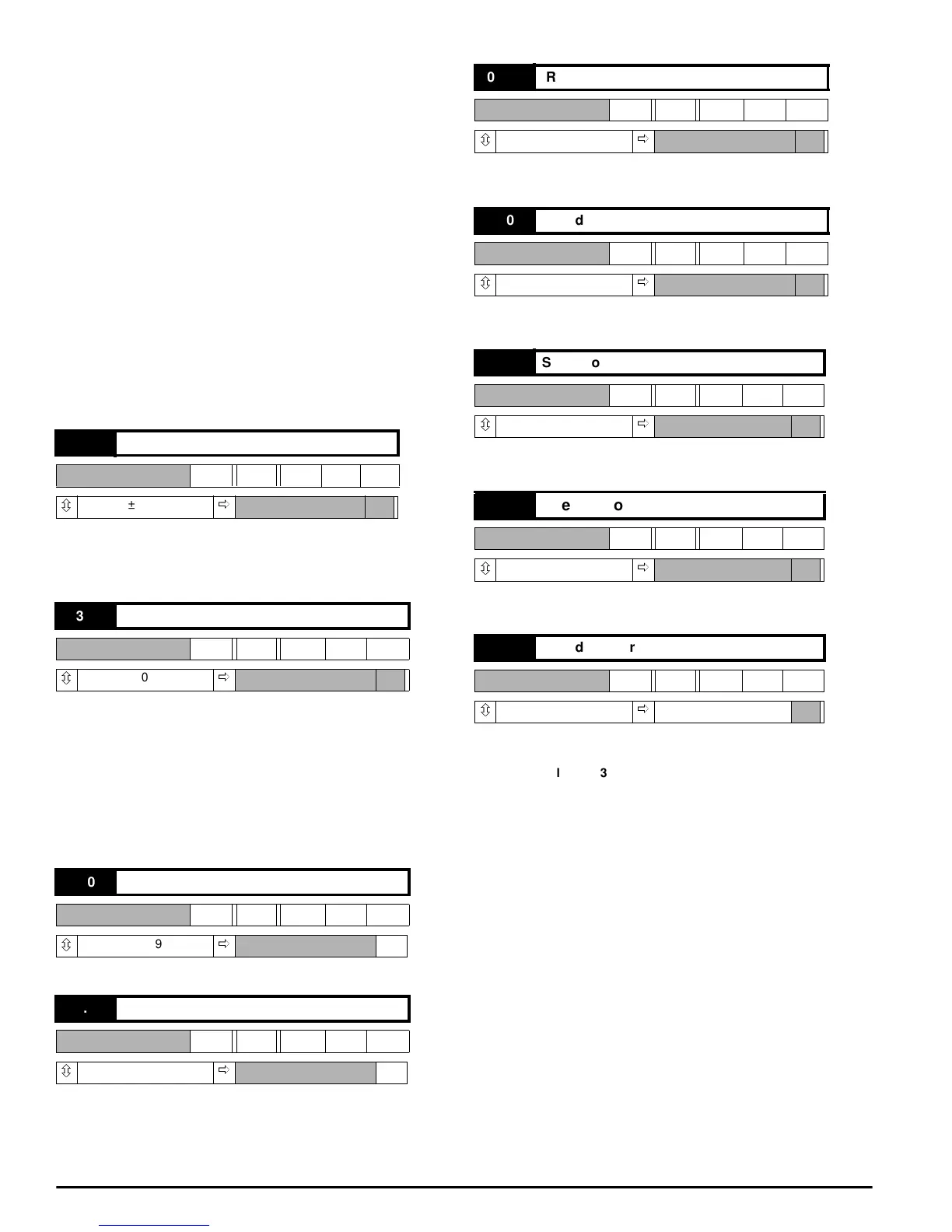
03.01 Final speed demand
RO Bi
ô
±1000
ð
03.02 Speed feedback
RO Bi
ô
±1000
ð
03.03 Speed feedback (rpm)
RO Bi
ô
±1999
ð
rpm
03.04 Armature voltage
RO Bi
ô
±1000
ð
V
03.05 IR Compensation output
RO Bi
ô
±1000
ð
03.06 Speed error
RO Bi
ô
±1000
ð
03.07 Speed loop output
RO Bi
ô
±1000
ð
03.08 Speed error integral
RO Bi
ô
±1000
ð
03.09 Speed loop proportional gain
RW Uni
ô
0~255
ð
080
Factor
ValueOf03.09
8
----------------------------------------
=