Mentor ll User Guide 47
Issue Number: 12 www.controltechniques.com
Menu 04: Current Selection and Limits
The principal input is the speed loop output 03.07 in combination, for
torque- or current-control modes, with the torque reference 04.08.These
inputs become the current demand to which an offset or trim option may
be applied. The result is then subject to an over-riding limitation derived
from several sources including the speed feedback. Six bit-parameters
determine the mode of control speed control, current control, number of
quadrants, etc.
A feature in this menu is the facility to apply a second current limit
(04.07) automatically refer to 04.10, 04.18 and 04.19 which allow
current limit 2 to be applied after a chosen time delay. This is appropriate
to applications where the initial load torque on start-up is high, but after
some period becomes less, as with some mechanical mixing processes,
for example.
The current demand signal is the controlling input to the current loop
when the Drive is being operated in speed-control mode. The signal is
subject to limitation by 04.04, 04.05 and 04.06 before being passed to
the current loop.
Current demand final output, to the current loop (Menu 05) after limits
have been applied.
This is the limiting value of current demand and is the result of the
speed-dependent current taper calculation or I-limit 2 (if selected),
whichever is the lower.
This parameter provides symmetrical current-limitation for bridges 1 and
2 and is the datum level from which the current taper functions operate
refer to 04.20 and 04.21. I-limit 1 can be used in application where the
motor kW rating is somewhat less than that of the Drive, as an
alternative to changing the fixed current-burden resistors.
Determines the maximum limit of current demand when bridge 1, the
positive bridge, is conducting. It causes any demand for current in
excess of the limit set point to be ignored.
Determines the maximum limit of current demand when bridge 2, the
negative bridge, is conducting. It causes any demand for current in
excess of the limit set point to be ignored.
Available as an additional current limit. Applies to both bridges. The
Drive can be programmed, if desired, to select 04.05 automatically at a
programmed time interval after a RUN signal. Refer to 04.10, 04.18 and
04.19.
This value is an input to the current loop and can be selected for use in
applications requiring direct control of current (motor torque).
Current offset is used to apply a trim to the current demand 04.01.
Set 04.10 = 1 to select current limit bridge 2. Can be caused to change
automatically refer to 04.18 and 04.19.
Set 04.11 = 1 to select current offset.
Set 04.12 = 1 to select. Operates in conjunction with 04.13 to configure
the Drive for speed control or any of three modes of torque control. Refer
to 04.13.
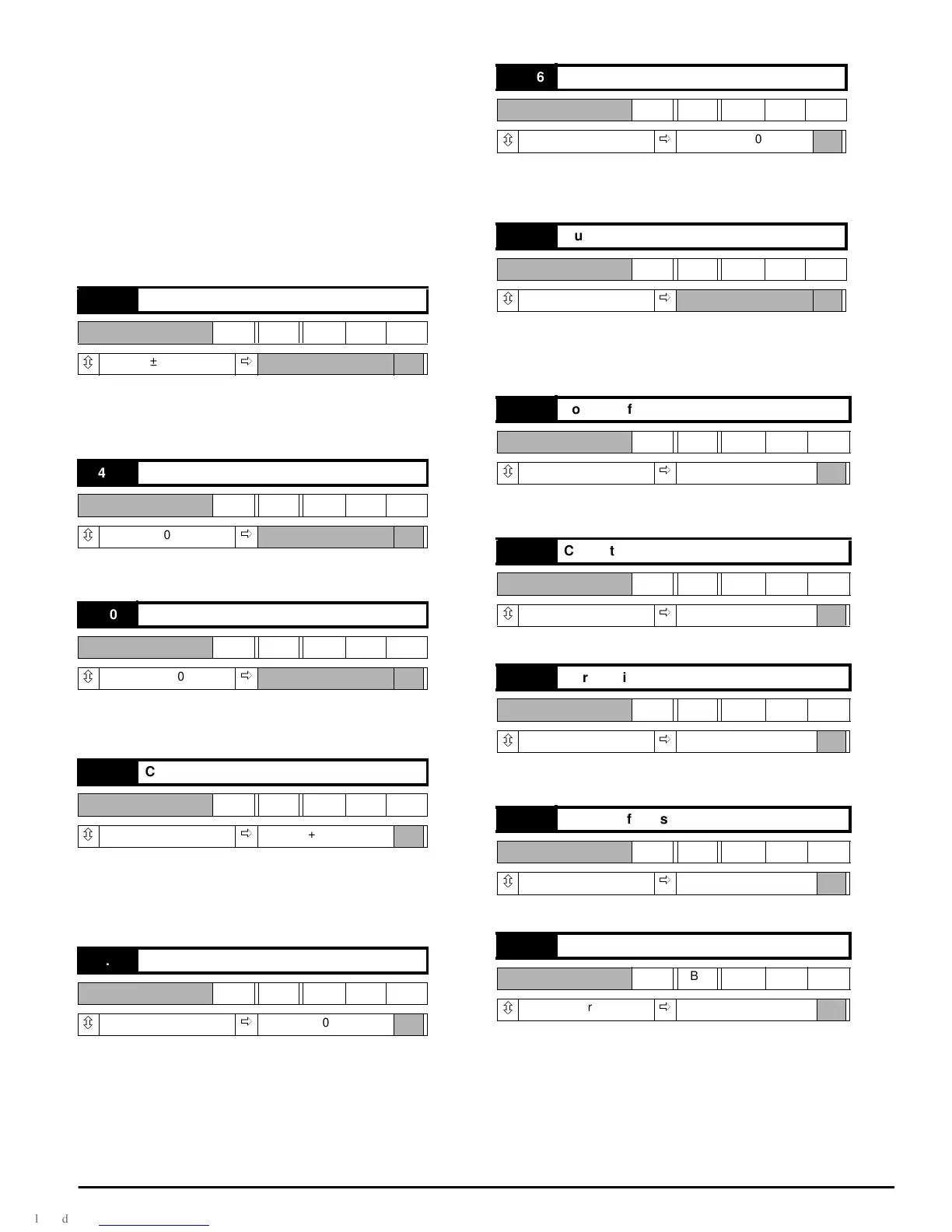
04.01 Current demand
RO Bi
ô
±1000
ð
04.02 Final current demand
RO Bi
ô
±1000
ð
04.03 Over-riding current limit
RO Bi
ô
±1000
ð
04.04 Current limit (taper start point)
RW Uni
ô
0~1000
ð
+1000
04.05 Current limit bridge 1
RW Uni
ô
0~1000
ð
+1000
04.06 Current limit bridge 2
RW Uni
ô
0~1000
ð
+1000
04.07 Current limit 2
RW Uni
ô
0~1000
ð
04.08 Torque reference
RW Bi
ô
±1000
ð
+000
04.09 Current offset
RW Bi
ô
±1000
ð
+000
04.10 Current limit bridge 2 selector
RW Bit
ô
0or1
ð
0
04.11 Current offset selector
RW Bit
ô
0or1
ð
0
04.12 Mode bit 0
RW Bit
ô
0or1
ð
0 (not selected)