46 Mentor ll User Guide
www.controltechniques.com Issue Number: 12
Speed reference fed into the speed loop without passing through the
ramps.
If 03.19 is set to 1, and Ref ON (01.11) = 1, the Hard Speed reference
(3.18) is added at the speed loop summation point.
If 03.20 = 1 when using armature voltage as the speed feedback, speed
will decrease as load increases.
A typical application, for example, is a mechanical blanking press fitted
with a heavy flywheel. Applying IR droop prevents the Drive from
delivering a sudden increase of current at the moment of impact (sudden
increase of torque demand). It is better that the Drive should deliver
energy to the flywheel during the whole operating cycle rather than
mostly at the moment of impact.
When 03.21 = 1, Ramp output is added at the speed loop summation
point.
Used as a fine trim on the speed reference signal to correct, or
introduce, a small offset.
A value of 0 gives an offset of -8 units, the default value gives zero offset
and a value of 255 gives an offset of +8 units.
Thethresholdmaybeadjustedtoanyvalueupto25.5%ofmaximum
speed. Refer also to 10.09.
The derivative term of the PID in the speed loop may use one of three
sources
1 = Speed error 03.06
Damping changes in speed demand and feedback
2 = Speed reference 03.01
Velocity feed-forward
3 = Speed feedback 03.02
Damping on feedback only (feedback forcing).
where f =supply frequency
A low-pass filter to reduce the effect on the speed error signal (03.04)of
interference from a noisy tachogenerator (tachometer), for example.
Monitors the tacho input measurement. The tacho potentiometer is used
to scale the feedback signal such that at full motor speed, 03.26 = 1000.
Units displayed = 0.1% of full speed per increment.
Setting this parameter at 1 will increase the speed loop proportional gain
by a factor of 4.
When set the speed loop gains are reduced by a factor of 8 so that:
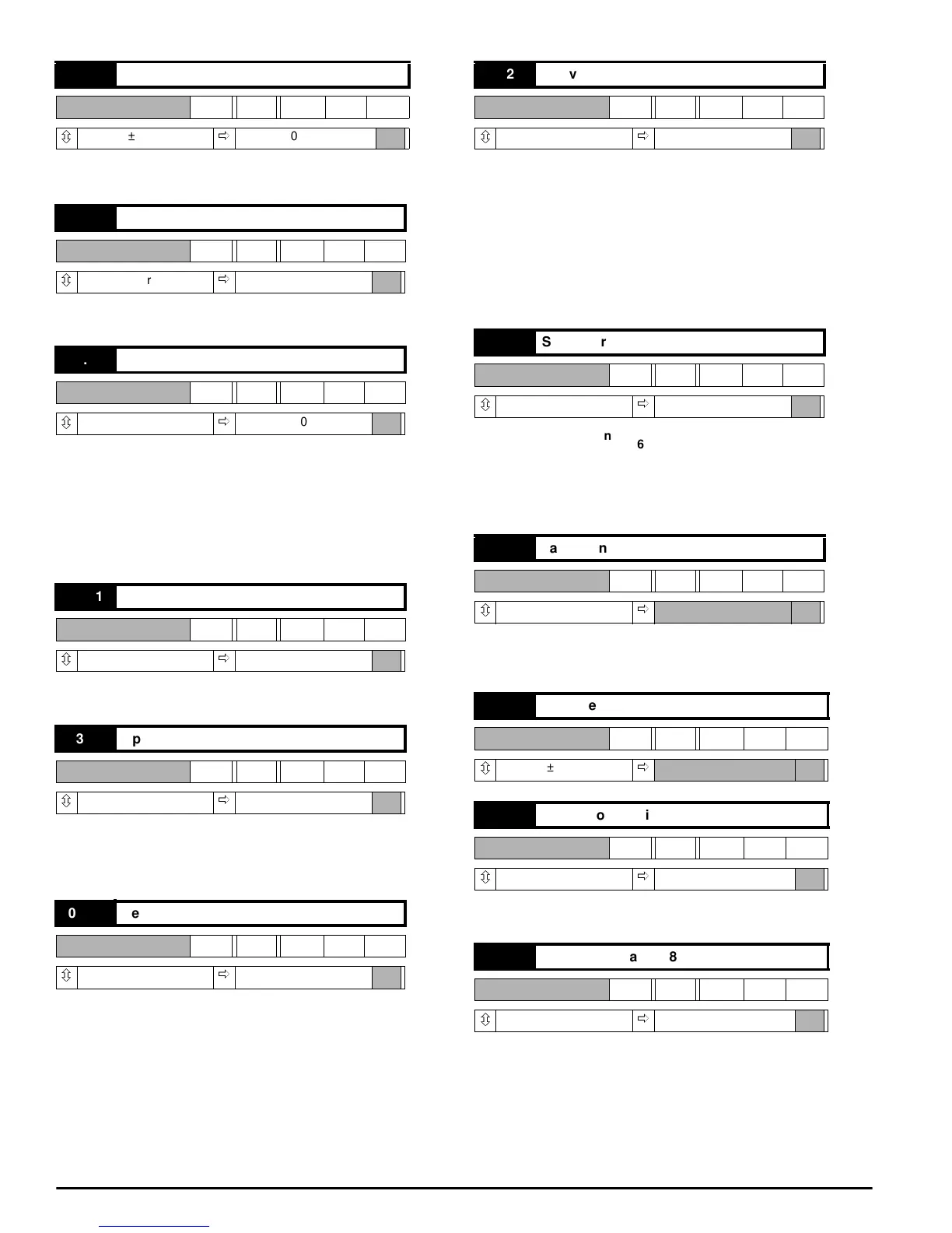
03.18 Hard speed reference
RW Bi
ô
±1000
ð
(07.11)
03.19 Hard speed reference selector
RW Bit
ô
0or1
ð
0
03.20 IR droop selector
RW Bit
ô
0or1
ð
0
03.21 Ramp output selector
RW Bit
ô
0or1
ð
1
03.22 Speed offset fine
RW Uni
ô
0~255
ð
128
03.23 Zero speed threshold
RW Uni
ô
0~255
ð
15
03.24 Derivative term source
RW Uni
ô
1,2 or 3
ð
1
03.25 Speed error filter
RW Uni
ô
0~255
ð
128
03.26 Tachogenerator input
RO Bi
ô
±1000
ð
03.27 Reserved
RO Bi
ô
±1000
ð
03.28 Proportional gain x 4
RW Bit
ô
0or1
ð
0
03.29 Speed loop gains / 8
RW Bit
ô
0or1
ð
0
FilterTime Cons ttan–
256
6f 03.05()×
-------------------------------
=
PGAIN
03.09
64
---------------
=
IGAIN
03.10 6× f×
2048
--------------------------------
=