Mentor ll User Guide 17
Issue Number: 12 www.controltechniques.com
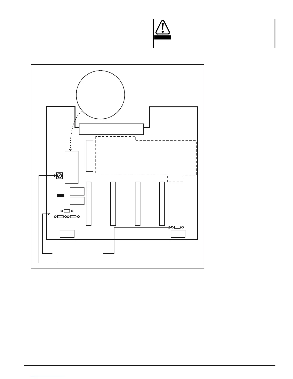
6.4 Control Connections
Refer to Figure 6-2, Figure 6-3, Figure 6-4, and Figure 6-5. Also section
6.5 Terminals index on page 18 and section 6.6 Terminals classified on
page 19.
Figure 6-4 Location of principal components on PCB MDA2B issue
(revision) 2
Isolation
The control circuits and terminals are isolated from the
power circuits only by basic insulation to IEC664-1. The
installer must ensure that all external control circuits
are separated from human contact by at least one layer
of insulation rated for use at the AC supply voltage.
SW1A = Pos
SW1B = +5V
SW1C = +12V
SW1D = +15V
SW1F = 10 - 50V
SW1G = 50 - 200V
SW1H = 60 - 300V
SW1A
SW1B
SW1C
SW1D
SW1F
SW1G
SW1H
1
2
3
4
5
6
7
8
9
10
TB1
31
32
33
34
35
36
37
38
39
40
TB4
21
22
23
24
25
26
27
28
29
30
TB3
11
12
13
14
15
16
17
18
19
20
TB2
+10V
-10V
SPEED
GP1
GP2
GP3
GP4
THERM
TACHO -
TACHO+0V
CURR
DAC1
DAC2
DAC3
ST1
ST2
ST3
ST4
ST5
0V
F1(STOP)
F2(IR)
F3(IF)
F4(RR)
F5(RF)
F6
F7
F8
F9
F10
ENABLE
RESET
+24V
POLE
NC
NO
POLE
NC
NO
0V
R10
R11R12
PL4
PL3
SK3
Option)
MDA2B
Feedback encoder
Serial port
Tachogenerator (tachometer) potentiometer
R6, R10, R11, R12 should match the
characteristic impedance of the cable
(approx. 120 for twisted pair)
Ω
Mounting pillars (standoffs)
for terminating resistors
{
WARNING