Mentor ll User Guide 67
Issue Number: 12 www.controltechniques.com
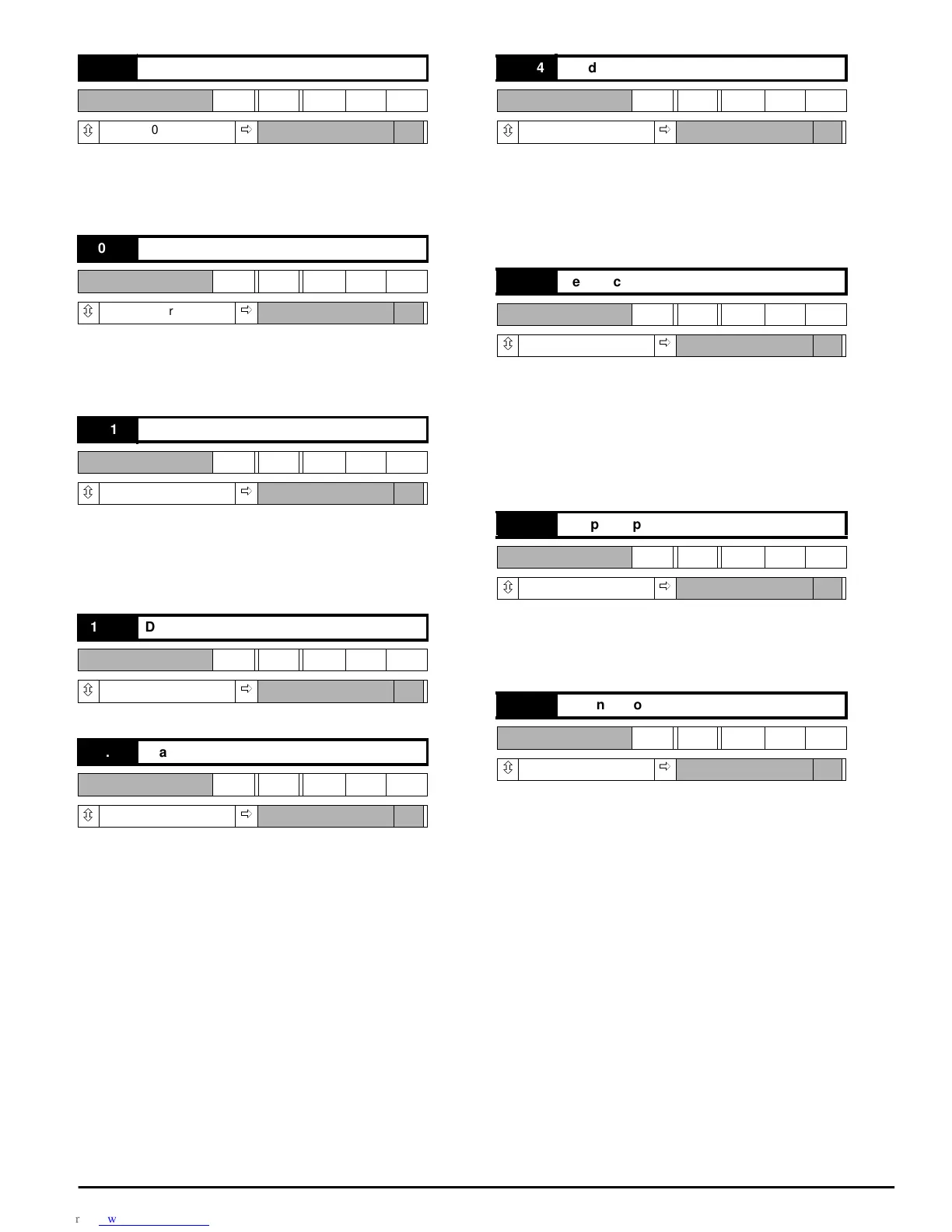
0=speednotzero
1=zerospeed
Set if speed feedback 03.02 < zero speed threshold 03.23. Refer to
10.01 and 10.02
0=clampnotactive
1=clampactive
Set when the armature voltage clamp is activated. Prevents the voltage
from increasing further. Refer to 03.15.
0 = L1 L3 L2
1 = L1 L2 L3
Rotation is detected from L1, L2, L3.
NOTE that connection to E1 and E3 must also be correct - refer to
Figure 6-2 and Figure 6-3.
1 = Drive is powered-up and has not tripped.
0 = no alarm condition present
1 = alarm condition present, impending sustained-overload trip
Indicates that the Drive is in an overload condition and will eventually trip
on sustained overload 10.18 if the overload condition is not removed.
The time taken to trip is dependent on the settings of 05.06 and 05.07
and on the magnitude of overload.
Visual indication that the alarm has been actuated is given by the Alarm
LED (flashing). External signal also provided through status logic output
ST3 to terminal TB2-17 provided that source parameter 09.19 is at its
default value.
0 = field healthy (normal)
1=fieldfailed
Indicates that no current is being drawn from the internal field supply (or
the FXM5 optional external field control unit if installed).
The field loss trip does not operate when the direct firing angle control is
selected (6.19).
0 = speed feedback present
1 = speed feedback absent or polarity reversed
Indicates no feedback signal, or reversed polarity. Applies equally to
tachogenerator (tachometer) and encoder (pulse tach.) feedback,
whichever is selected. Loss of feedback is not detected until the firing
angle has advanced to the point where the value of 05.03 (firing angle)
>767. This condition can be prevented from tripping the Drive by
disabling feedback loss detection 10.30.
0 = healthy (normal)
1 = supply/phase loss
Indicates loss of one or more input phases connected to L1, L2, L3. Can
be disabled by means of 10.31.
0 = no overcurrent peak detected
1 = overcurrent peak detected
Indicates that a current peak >2 x (max. current according to the burden
resistor installed) has occurred. The result is that firing pulses are
immediately suppressed, shutting the Drive down.
10.09 Zero speed
RO Bit
ô
0or1
ð
10.10 Armature voltage clamp active
RO Bit
ô
0or1
ð
10.11 Phase rotation
RO Bit
ô
0or1
ð
10.12 Drivehealthy(normal)
RO Bit
ô
0or1
ð
10.13 Alarm (I x t)
RO Bit
ô
0or1
ð
10.14 Field loss
RO Bit
ô
0or1
ð
10.15 Feedback loss
RO Bit
ô
0or1
ð
10.16 Supply or phase loss
RO Bit
ô
0or1
ð
10.17 Instantaneous trip
RO Bit
ô
0or1
ð