42 Mentor ll User Guide
www.controltechniques.com Issue Number: 12
4 Quadrant
1 Quadrant
When set to 1, allows the Drive to respond to a bipolar analog speed
reference (01.02) in which case the direction of rotation is determined by
the bipolar signal. Positive polarity causes forward
rotation; negative polarity, reverse. When 01.10 = 0 the Drive responds
in a unipolar mode, negative-polarity signals being treated as a zero
speed demand.
Applies the speed reference to 01.03, pre-ramp reference. Defaults to
zero if terminal TB3-21 (Run permit) is de-activated. Cannot be set to 1
unless terminal TB3-21 is activated. Is also subject to the status of the
normal logic functions refer to Menu 08. Controlled in default by
terminals TB3-22, TB3-23, TB3-24, TB3-25
When normal logic functions are disabled a programmable input can be
used to control parameter 01.11 only if a RUN PERMIT signal is present.
Reverse select inverts the polarity of the speed reference signal. It has
the effect (in a four-quadrant Drive) of reversing the sense of the speed
signal without regard to the nominal direction of motor rotation. Default
value 01.12 = 0, inversion not applied. Controlled in default by terminals
TB3-22, TB3-23, TB3-24, and TB3-25.
Inch select replaces all other speed demand references by the inch
reference 01.05. Default value 01.13 = 0, normal speed reference
applied. Controlled in default by terminals TB3-22, TB3-23.
The two reference selectors 01.14 and 01.15 in combination allow any
one of the four speed references 01.17 to 01.20 to be selected.
The two reference selectors 01.14 and 01.15 in combination allow any
one of the four internal speed reference 01.17 to 01.20 to be selected.
See table above.
Prevents the starting of the Drive until the analog speed reference,
external or internal, is near to zero:
-8 < 01.01 < +8 (values in 0.1% of full speed)
This facility is convenient in applications where for safety or process
reasons the operator determines speed by observations of the process,
for example extrusion, or traction Drives.
Reference 1, parameter 01.17 is the default destination of the external
speed reference (terminal TB1-3) through the programmable input
07.15.
Reference 2, parameter 01.18, default +300.
References 3 and 4, parameters 01.19 and 01.20, default to
programmable inputs GP3 (TB1-6) and GP4 (TB1-7) respectively.
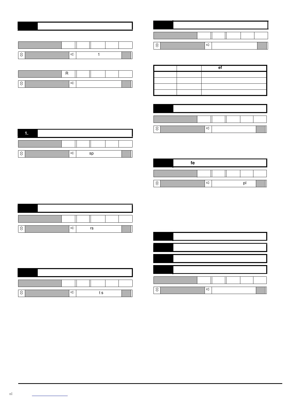
01.10 Bipolar reference selector
RW Bit
ô ð
1
RW Bit
ô ð
0
01.11 Reference ‘ON’
RW Bit
ô ð
0, no speed reference
01.12 Reverse selector
RW Bit
ô ð
0,reverse not selected
01.13 Inch selector
RW Bit
ô ð
0, inch not selected
01.14 Reference selector 1
RW Bit
ô ð
0
1.14 1.15 Reference Selected
00 1.17
10 1.18
01 1.19
11 1.20
01.15 Reference selector 2
RW Bit
ô ð
0
01.16 Zero reference interlock
RW Bit
ô ð
0, inhibit not applied
01.17 Reference 1
01.18 Reference 2
01.19 Reference 3
01.20 Reference 4
RW Bi
ô ð
As stated below