Mentor ll User Guide 71
Issue Number: 12 www.controltechniques.com
Designations:
The displayed value is the decimal equivalent of the bit-pattern.
Disables the normal functions of the keypad LED indicators (with the
exception of Drive Ready) and renders them programmable. By setting
11.22 = 1, normal LED functions (with the exception of Drive Ready ) can
be controlled via the serial interface or processor 2 special application
software. The LEDs display the binary equivalent of the value in 11.21.
Setting of 1 = MDA6 High voltage (660V)
If the High voltage (660V) MDA6 power board is to be used for a high
voltage Mentor II, this parameter must be set = 1.
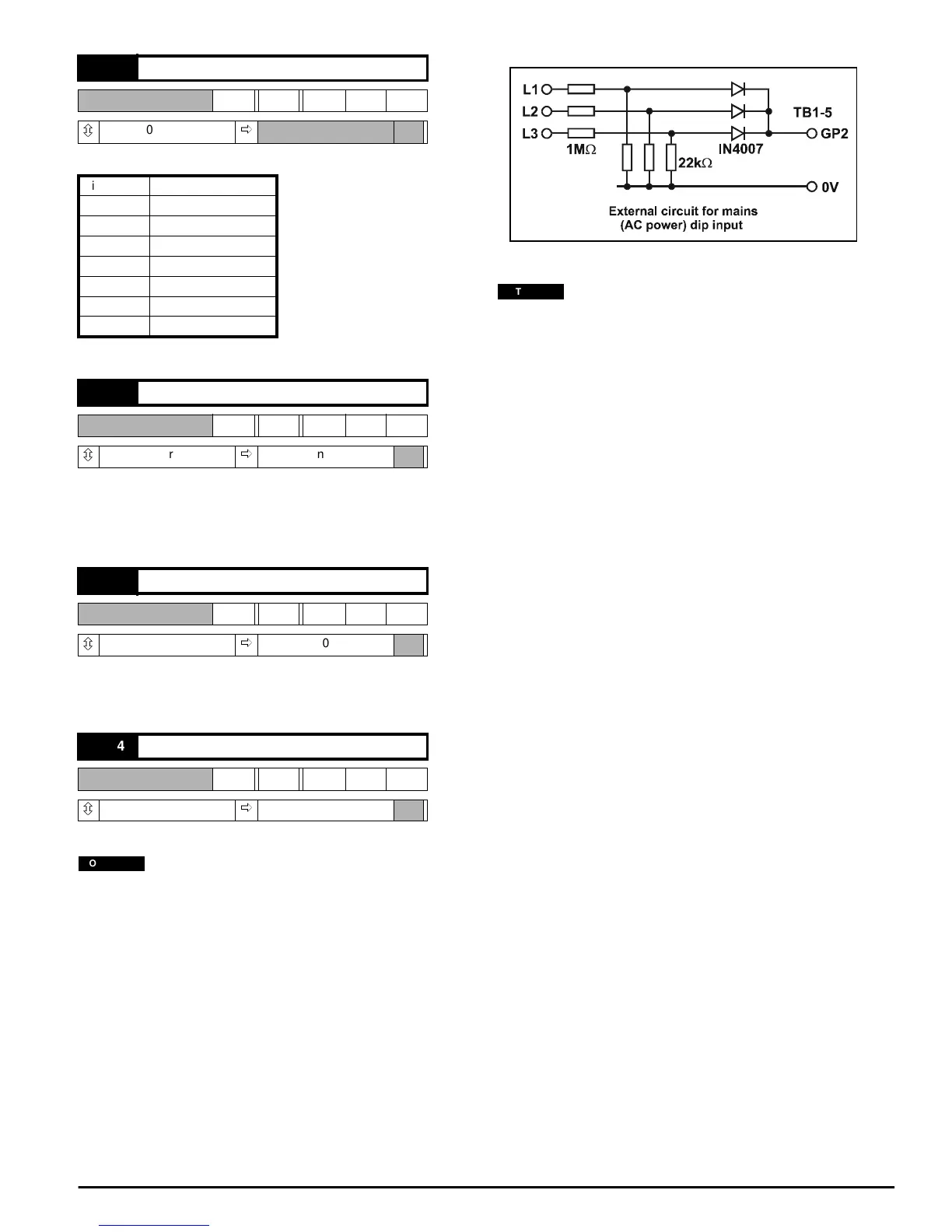
Default 1 = Enable ride-through
In order to maximize the mains dip ride-through capability of the
Mentor II it is necessary to connect the circuit shown in Figure 8-7.
Software version V3.1.0, or later, must be installed.
Analog input GP2 (refer to Menu 07) is set up as a mains healthy
(AC power normal) input when parameter 11.24 = 1. When set up in
this way, if the voltage on terminal TB1-5 (GP2) falls below the 1 V
threshold, the Drive disables firing immediately and shuts the
display off to reduce power consumption. When the Drive detects
that the supply has been established for 40mS, it will reset and
restart provided that the appropriate RUN and ENABLE commands
are still present. The Drive will typically take 340ms to restart after a
mains dip.
Figure 8-7
With software version V4.2.0 and earlier the Drive healthy relay
would change state to indicate a fault if the Drive detected a mains
dip.
11.21 LEDs byte
RW Uni
ô
0~255
ð
Bit 7 Alarm
Bit 6 Zero speed
Bit 5 Run forward
Bit 4 Run reverse
Bit 3 Bridge 1
Bit 2 Bridge 2
Bit 1 At speed
Bit 0 Current limit
11.22 Disable normal LED functions
RW Bit
ô
0or1
ð
0, enabled
11.23 High voltage MDA6
RW Bit
ô
0or1
ð
0
11.24 Mains (AC power) dip ride-through
RW Bit
ô
0or1
ð
0
NOTE
NOTE