88 Mentor ll User Guide
www.controltechniques.com Issue Number: 12
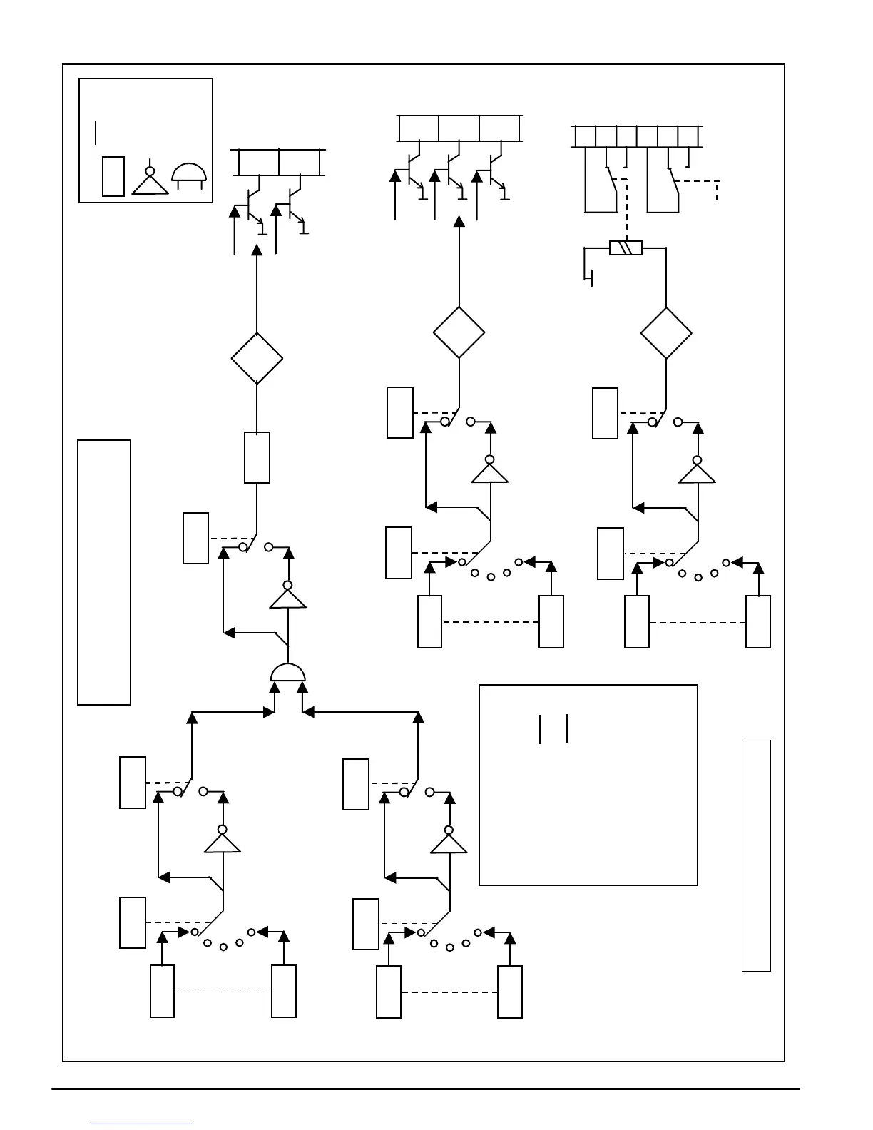
Delay
Status output
ST1 09.11
ST2 09.17
Status
output
ST6
Invert status
output ST6
Status
output
Status
source
selector
ST1
ST2
15
16
34
35
36
37
38
39
Default
Zero
speed
Default
Drive
ready
Controlled by
parameter
10.12 (RO)
Relay Outputs
ST3
ST4
ST5
17
18
19
Open Collector
Transistor Outputs
09.xx
Status input
ST6
09.06
0
1
Status input
09.xx
0
1
Contact
loading
5A, 240V AC
09.26
09.xx
09.xx
09.25
ST3 09.19
ST4 09.21
ST5 09.23
ST3 09.20
ST4 09.22
ST5 09.24
ST3 09.03
ST4 09.04
ST5 09.05
Invert
status
output
09.xx
Invert
output
0
1
09.xx
ST1 09.12
ST2 09.18
ST1 09.01
ST2 09.02
&
Source 1 select Source 1 invert
Source 2 invert
Source 2 select
0
1
Status input
0
1
09.xx09.xx
09.xx
09.xx
Status input
ST1 09.07
ST2 09.13
ST1 09.08
ST2 09.14
ST1 09.10
ST2 09.16
ST1 09.09
ST2 09.15
Invisible parameters are in italics, eg 09.07
Menu 09 STATUS OUTPUTS
Ifthestatussourceisnotabitparameter,
the input to the “&” gate is taken as 1,
provided the other source is a bit parameter.
KEY
R/W logic
Logic ‘and’
&
Inversion
Status outputs 1 and 2 can be
any of the following functions
of any two bits:
OR A + B
NOR A + B
AND A x B
NAND A x B
For example:
09.07 = 1003 I lim
09.08 = no invert
09.09 = 1009 Z speed
09.10 = no invert
09.11 = no invert
ST1 = I lim AND Z speed = Stall
NOTE
ST5 becomes dedicated as
Bridge Selected output
when parameter 05.21 = 1
(12-pulse bridge lockout)