44
4 Mechanical Installation
4.1 Components Checklist
The major components of the CPS ES series energy storage system are shown below.
NOTE: The 250 kW / 559.1 kWh ESS has two battery cabinets and two 125 kW PCS modules in the same PCS cabinet.
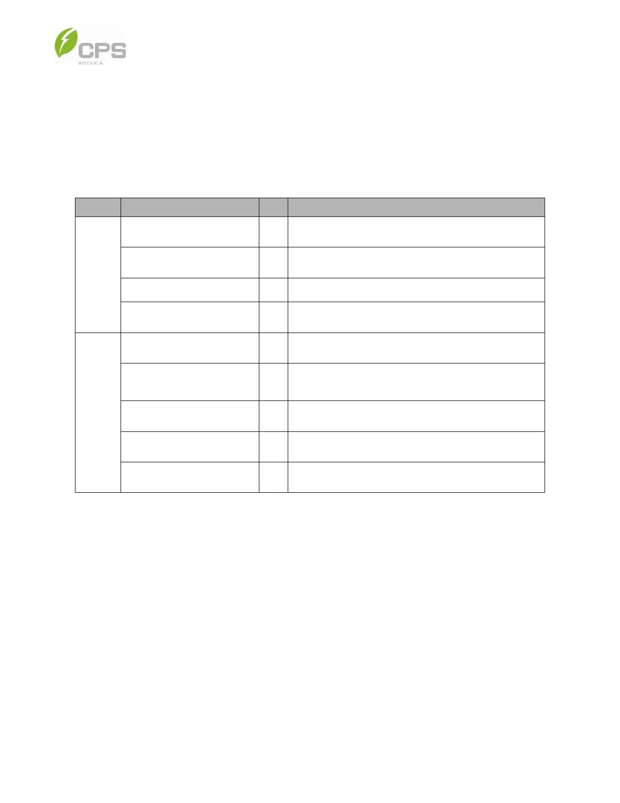
Table 4-1 125 kW / 279.55 kWh ESS Components
Item Qty. Note
Battery
cabinet
Battery packs 6
Includes power cables, MSD, communication cables, and
cell-level BMS assembled in the pack.
HV control box 1
Includes power cables, communication cables, power
supply, AC breakers, and DC insulation switch.
Fire suppression unit 1 Includes heat detector, smoke detector, and aerosol spray.
String level BMS 1
Calculates the SOC and SOH and controls the contactors
inside the HV control box.
PCS
cabinet
125 kW PCS module 1
Each 125 kW module includes one 62.5 kW master unit and
one 62.5 kW slave unit.
PCS cabinet power
distribution system
1
Includes circuit breakers, surge protectors, control relays for
emergency power-off button, and cabinet fan.
UPS 1
Provides backup power to the PCS control unit, networking
equipment, and control relays.
Transformer 1
Provides power to the battery cabinet liquid-cooling chiller,
BMS, and all control circuits inside the PCS cabinet.
PCS cabinet accessories 1 Includes base sealing plate.