22
2.6.4 PCS Cabinet Cable Entry
Cables within the ESS and between the ESS and other external equipment must be routed through the holes on the bottom of
the cabinet. All cables entering the cabinet must run through the cable tray or conduit for proper protection from corrosion and
rodents. After the cables are installed, fireproof putties must be applied to seal the holes.
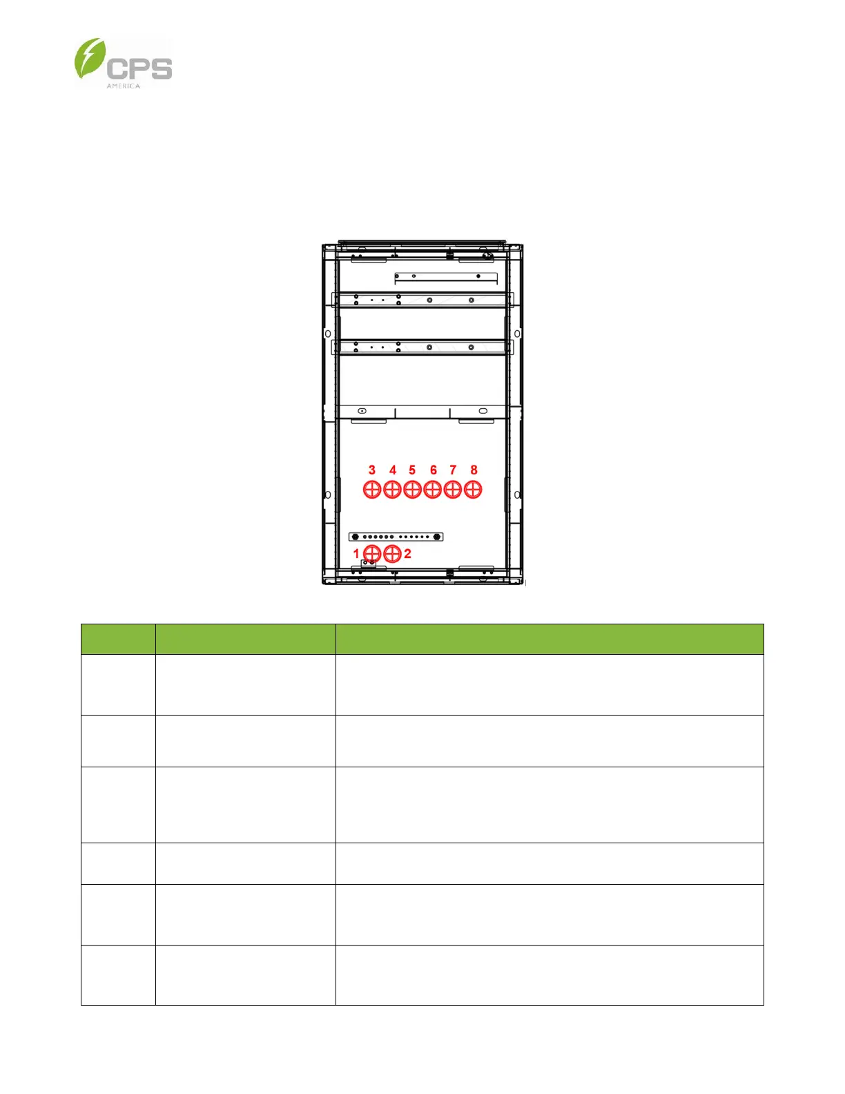
The cable slot locations are shown in the image below.
Figure 2-7 Layout of the PCS Cabinet Bottom Panel Cable Holes
No. Use Description
Hole 1
LV communication cable and
auxiliary power cable
For connecting the LV communication cable
between the PCS cabinet and the battery cabinet.
Hole 2
LV communication cable and
auxiliary power cable
For connecting the LV communication cable between the PCS cabinet
and the second battery cabinet (250 kW / 559 kWh configuration).
Hole 3 /
Hole 7
DC cables
If the battery cabinet is installed to the left of the PCS cabinet, the
DC cables will go through hole 3; if the battery cabinet is installed to
the right of the PCS cabinet, the DC cable will go through hole 7.
Hole 5
AC cables AC grid connection to the copper busbars of the PCS cabinet.
Hole 4 /
Hole 6
Grounding cable and DC
block auxiliary power cable
The ground cable and auxiliary power cable for the battery
cabinet BMS and liquid cooling chiller go through these holes.
Hole 8
Network cable
Three CAT6 Ethernet cables will go through this hole
to outside Internet service or third-party EMS integrators.