55
5.4.2 AC / DC Wiring Terminal Locations
Check the following items before wiring the cables:
1. Completely shut off the main supply of AC voltage from the grid side.
2. Check the AC voltage at the AC terminal busbar at the central bottom portion of the PCS cabinet.
3. Ensure that the DC insulation switch and AC breaker inside the PCS cabinet are in the OFF position.
NOTE: To ensure that the DC insulation switch is in the OFF position inside the battery cabinet, locate the white cover
with four (4) screws and take them out to flip the two AC breakers into OFF positions.
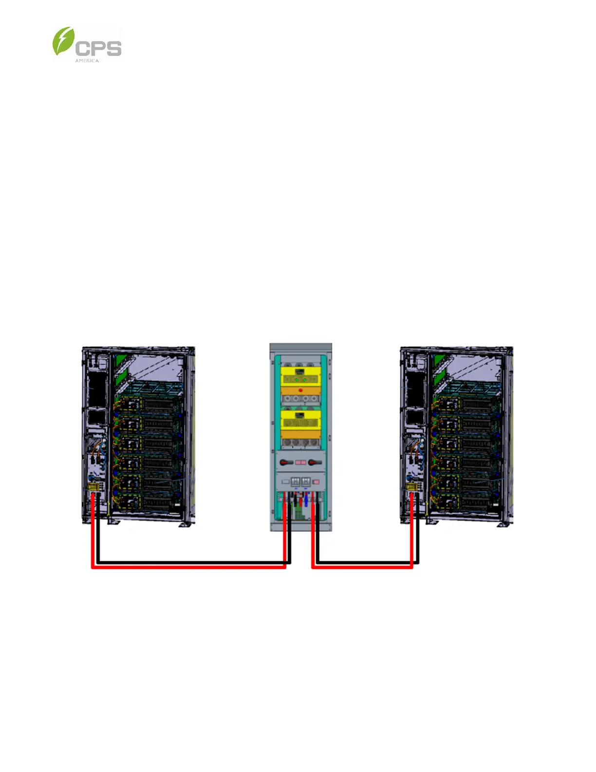
To connect the battery cabinet(s) to the PCS cabinet:
1. Open the door(s) of the battery cabinet(s).
2. Connect the power cables to the HV+/HV- terminals on the battery cabinet HV control box and the DC+/DC- terminals of
the PCS cabinet. The terminal locations are shown in Figure 5-2 below.
NOTE: The red and black cables shown already have the terminal screwed on the PCS busbar prior to shipping.
Figure 5-5 Battery Cabinet and PCS Connection
3. Plug the other end of the red and black cables into the HV control box; see Figure 5-2 above.
NOTE: The battery has a pre-cut opening for the main DC cable.