56
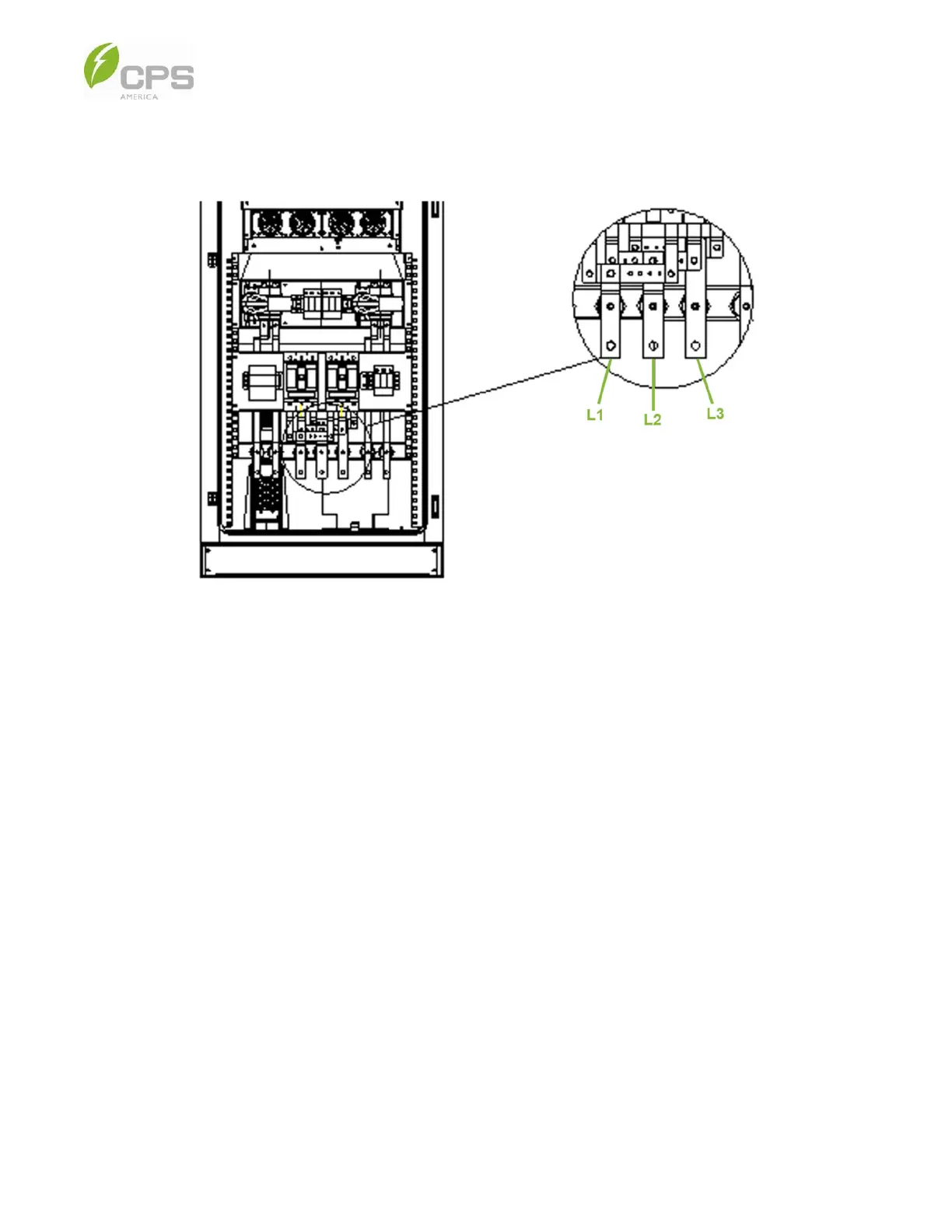
4. The AC terminals of the PCS cabinet are for connection to the utility service panel or micro-grid switch terminals. Open
the PCS cabinet door and remove the protective plate to access the copper busbar; the wiring location is shown in Figure
5-3 below.
Figure 5-6 PCS Cabinet AC Terminal Block
5. For a 250 kW system, screw one set of L1/L2/L3 lugs or two sets back-to-back.
6. Refer to the image and table below (Figure 5-1 and Table 5-1) for the recommended approach to wiring the AC, DC, and
communication cables through the holes and conduit.
NOTE: Each hole has a rubber protector; the holes are 1.97 in (50 mm) in diameter with the rubber protector and 2.36 in
(60 mm) in diameter without the rubber protector.