Page 7
TELECOM INTERFACETELECOM INTERFACE
The communicator facility of this Power Wave-8 controller has been designed to provide optimum flexibility in the way
in which alarm events are reported. This flexibility includes options for reporting to a central monitoring station using
Ademco Contact ID, a domestic reporting option using alternating siren tones, a format for reporting alarms to a
numeric pager and a powerful speech dialler.
In accordance with statutory requirements of Austel standards, we must bring the following points to your attention;
Connect the Telephone line via a Mode 3 lead (supplied) to the Mode 3 phone socket on the wall (not supplied). Using
a Mode 3 socket on the wall, allows the Power Wave-8 to cut off existing telephones or other devices connected to the
same phone line and seize the telephone line to ensure the alarm call can be made. The control panel is supplied with
an RJ11 socket and/or terminal blocks for connecting the panel to the telephone line. If using the RJ11 phone socket
on the PC Board, ensure that the supplied phone lead is used to connect the panel to the telephone line socket on the
wall.
All connections must comply with Australian Standards ACA TS008.
If using the (Optional) terminal blocks on the PCB, then the system must be wired in accordance with the diagram
below and the lead must comply with Australian Standards ACA TS008.
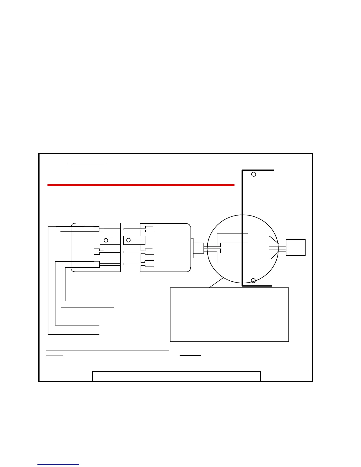
The following diagram shows how the Mode 3 (Type 600) plug should be wired to the Power Wave-8.
The transmit level from this device is set at a fixed level in accordance with Austel requirements and because of this,
there may be circumstances where this device does not give its optimum output level performance. Before reporting
such occurrences as faults, please check the line with a standard Austel approved telephone, and do not report a fault
unless the telephone performance is impaired.
This automatic dialling equipment shall not be set up to make calls to the " 000 " Emergency Service
600 Series Plug
600 Series Wall Socket
Australian Mode - 3 Connection Diagram
Bottom View Of The Mode 3 (Type 600) Plug And Wall Socket
Red
1
2
3 4
5
6
1
Red
Yellow
Black
5
2
3 4 6
POWER WAVE
CONTROLLER
“ + ” Line Out
“+ ” Line In
“ - ” Line In
“ - ” Line Out
Green
3 & 4 Not Connected
Black
Green
Yellow
TELEPHONE
LINE
( LINE IN )
TO INTERNAL
PHONES
( LINE OUT )
Line Out ( + )
to Phones
Common ( - )
To line in/out
Line In
from Street
Phone
Socket
This is the Bottom View of Power Wave PCB and of the
RJ-11 Plug/Socket with Line In/Out polarity indication
from the phone cord to the RJ-11 socket.
When the PCB is in the “Face (Components) Up”
position, these wires (and line in/out polarities) are
in reverse to the above diagram (Eg: “ + ” is towards
Top edge of PCB and “ - ” is towards bottom edge of
PCB.
Bottom View of Power Wave PCB
5 = “ + ” Line OUT
1 = “ - ” Line OUT
2 = “ - ” Line IN
6 = “ + ” Line IN
Mode 3 (Type 600) Plug And Wall Socket Wiring;
LINE-IN:
Terminal 6 = Tip-In = “ + ” side of Line-In from Street
Terminal 2 = Ring-In = “ - ” side of Line-In from Street
LINE-OUT:
Terminal 5 = Tip-Out = “ + ” side of Line-Out to Int. Phones
Terminal 1 = Ring-Out = “ - ” side of Line-Out to Int. Phones