2 — INSTALLATION AND WIRING
Curtis Model 1226 – September 2019
Return to TOC
pg. 12
e following considerations apply to the voltage range specications:
• To provide a sucient response rate while also allowing for eective ltering, the
controller reads the inputs’ signals at least every 1ms.
• When an analog input’s voltage is outside its voltage range, the controller generates an
Analog Out of Range fault.
• An analog input’s voltage range can be congured with the analog input’s Low and
High parameters.
• If you set an input’s High parameter above the input’s voltage range, the controller
will not check whether the input’s actual voltage exceeds the specied voltage.
Switch Inputs
e controller provides 13 digital switches. You use the Switch Assignment menu to assign functions
to switches; see page 49.
You can observe a digital input’s state with the Switch n eld; see Switches Menu on page 60.
Switches 3, 8, and 13 each provide an integrated LED driver that outputs the switch’s status. For more
information, see page 13.
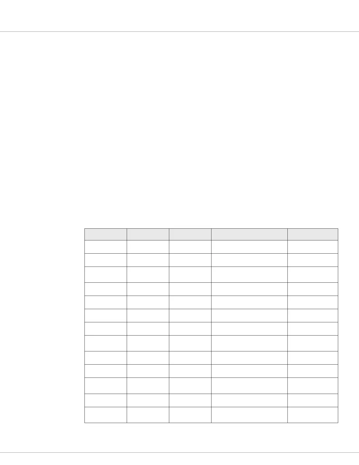
Table 9 describes the switch inputs.
Table 9 Switch Inputs
Switch Input Pin Number Analog Input Typical Function Switch Type
1 J3-7 1 Throttle pot wiper High active
2 J3-6 2 Speed limit pot input High active
3 J3-4 3 Emergency reverse NC input
• High active
• LED driver 3
4 J3-16 4 Throttle pot high High active
5 J1-6 5 Motor temperature sensor input Low active
6 J1-2 6 Speed sensor input Low active
7 J3-3 Interlock input High active
8 J3-8 Reverse input
• High active
• LED driver 2
9 J3-9 Push input High active
10 J3-14 Emergency reverse NO input High active
11 J3-15 Charge inhibit
• Charge inhibit
• Low active
12 J3-17 Forward input High active
13 J3-18 Mode input
• High active
• LED driver 1